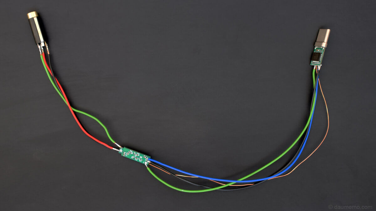
Today is the continuation of the DIY micro headphone amplifier. I have already talked about it in my previous two posts where I have introduced the idea with a prototype and where I have talked about custom made PCB dedicated for this project. So, todays topic is how I have soldered the amplifier.
Other post parts
- DIY portable headphone amplifier based on an INA1620 chip and TPS65135 (Part 1)
- DIY Micro PCB Headphone Amplifier (Part 2)
- Micro USB-C to 3.5mm Adapter and Headphone Amplifier (Part 3) (This page)
- DIY Micro USB-C to 3.5mm Adapter and Headphone Amplifier (Part 4)
Table of contents
Soldering the power circuit
The first step was to solder the power circuit, so I could check if it works as expected and outputs needed voltages, which are around +5V and -5V. The IC is in QFN package which means that it does not have any pins sticking out of the chip – the soldering is possible only with a hot air soldering solution (for example like this one).
So, first goes the IC (which is TPS65135 by the way) into the board and then all other components needed for the circuit. All other components apart the IC were soldered in using a regular soldering iron.
After that, I checked if the PSU circuit worked and, of course, it did not. I tried to resolder the IC, but it did not help. Finally, I found out that I had made a mistake in the PCB. The amplifier’s IC pad was connected to negative power supply voltage and ground simultaneously. So, I drilled out (picture below) the via which connects IC’s pad to GND and everything worked as needed.

After that, I have soldered all other components into the board.

If you haven’t read the second part and are wondering from where I have got the boards manufactured, I got them sponsored from PCBWay.
Amplifier testing
When I have got the PCB fully soldered, the next step was to test it out. So, the simplest way to test an amplifier is to connect it to an audio source and some headphones 😀

As you can see it in the photo above, for testing purposes I had an USB-C DAC connected to the amplifier and its output connected to an audio jack. Audio source was my smartphone.
As I have already stated in previous post, this amplifier can drive both, low and high impedance headphones without problems (although it is more intended for high impedance headphones).
Final soldering
After a simple test with 32 Ohm and 300 Ohm headphones, I needed to solder the PCB and the 3.5mm audio jack together.
Both, the jack and the PCB are tiny – it is hard to hold them together while soldering, so I have 3D printed a simple holder to do the holding job:

It perfectly aligns the PCB with the audio connector pins, so I didn’t need to worry about that the joint would soldered awry.
The whole setup while soldering looked like this:

And finally, the final assembly after soldering:

Final testing
The final audio testing was executed the same as the previous one, but now with the final PCB-audio jack assembly.

Summary
So, the final tiny amplifier came out as expected – tiny, portable, capable of driving high impedance headphones. It still requires some enclosure, but it is next post’s topic. The final idea is to have an USB-C DAC connected to this amplifier – which will make it an USB-C adapter (as there are many of these available in the market), but with additional audio amplification stage (to my knowledge there is no such device in the market).


