After the first part with the OrangePi Zero, there are two things left to do: add some buttons, so it will be possible to reset or power down the device without going to the OctoPrint’s WEB UI and make some kind of casing, so it won’t be just a bare board lying on a desk.
To read inputs from buttons WiringOP library will be used. Whole idea is more or less taken from an another tutorial, but instead of OrangePi PC, OrangePi Zero was used whit additional C code modifications.
Installing WiringOP library
As I am with a Windows machine, I am using Putty to SSH remotely to OrangePi Zero.
After connecting to OrangePi we will need to download WiringOP library to any available folder (in this case ‘downloads’ will be used):
mkdir downloads
cd downloads
git clone https://github.com/zhaolei/WiringOP.git -b h3
After that, let’s go to WiringOP folder and build the library:
cd WiringOP/
sudo ./build
To check if everything went as expected, you can run a command:
gpio readallYou should get similar output to:
 +-----+-----+----------+------+---+-Orange Pi+---+---+------+---------+-----+--+
 | BCM | wPi |   Name   | Mode | V | Physical | V | Mode | Name     | wPi | BCM |
 +-----+-----+----------+------+---+----++----+---+------+----------+-----+-----+
 |     |     |     3.3v |      |   |  1 || 2  |   |      | 5v       |     |     |
 |  12 |   8 |    SDA.0 | ALT5 | 0 |  3 || 4  |   |      | 5V       |     |     |
 |  11 |   9 |    SCL.0 | ALT5 | 0 |  5 || 6  |   |      | 0v       |     |     |
 |   6 |   7 |   GPIO.7 | ALT3 | 0 |  7 || 8  | 0 | ALT3 | TxD3     | 15  | 13  |
 |     |     |       0v |      |   |  9 || 10 | 0 | ALT3 | RxD3     | 16  | 14  |
 |   1 |   0 |     RxD2 | ALT3 | 0 | 11 || 12 | 0 | ALT3 | GPIO.1   | 1   | 110 |
 |   0 |   2 |     TxD2 | ALT3 | 1 | 13 || 14 |   |      | 0v       |     |     |
 |   3 |   3 |     CTS2 |   IN | 1 | 15 || 16 | 0 | ALT3 | GPIO.4   | 4   | 68  |
 |     |     |     3.3v |      |   | 17 || 18 | 0 | ALT3 | GPIO.5   | 5   | 71  |
 |  64 |  12 |     MOSI | ALT4 | 0 | 19 || 20 |   |      | 0v       |     |     |
 |  65 |  13 |     MISO | ALT4 | 0 | 21 || 22 | 0 | ALT3 | RTS2     | 6   | 2   |
 |  66 |  14 |     SCLK | ALT4 | 0 | 23 || 24 | 0 | ALT4 | CE0      | 10  | 67  |
 |     |     |       0v |      |   | 25 || 26 | 0 | ALT5 | GPIO.11  | 11  | 21  |
 |  19 |  30 |    SDA.1 | ALT5 | 0 | 27 || 28 | 0 | ALT5 | SCL.1    | 31  | 18  |
 |   7 |  21 |  GPIO.21 |   IN | 1 | 29 || 30 |   |      | 0v       |     |     |
 |   8 |  22 |  GPIO.22 |   IN | 1 | 31 || 32 | 0 | ALT3 | RTS1     | 26  | 200 |
 |   9 |  23 |  GPIO.23 |   IN | 1 | 33 || 34 |   |      | 0v       |     |     |
 |  10 |  24 |  GPIO.24 |   IN | 1 | 35 || 36 | 0 | ALT3 | CTS1     | 27  | 201 |
 |  20 |  25 |  GPIO.25 | ALT5 | 0 | 37 || 38 | 0 | ALT3 | TxD1     | 28  | 198 |
 |     |     |       0v |      |   | 39 || 40 | 0 | ALT3 | RxD1     | 29  | 199 |
 +-----+-----+----------+------+---+----++----+---+------+----------+-----+-----+
 | BCM | wPi |   Name   | Mode | V | Physical | V | Mode | Name     | wPi | BCM |
 +-----+-----+----------+------+---+-Orange Pi+---+------+----------+-----+-----+
But you should notice that the pin-out shown above is not the same as on a real OrangePi Zero:

Finding needed pins
Nevertheless, we still will use the library just with a particular logic suitable for a OrangePi Zero. For example, I am going to use GPIOs 198 and 199, which are physical 8th and 10th pins on a board pin header. Using the table above, GPIO 198 translates to 28th WiringOP lib’s pin and GPIO 199 – 29th WiringOP pin. So, we need to remember number 28 and 29 which will be connected to two pushbuttons.
Also, at this point you can connect two buttons to the GPIO 198 and GPIO 199 pins. One end of the button goes to the GPIO pin, another end – to GND. These buttons will help to test if the following C code works correctly.
Creating a C file
Next thing to do is to create a .c file with a program code which will do the needed logic. I have modified the code from the tutorial mentioned earlier.
So, we need to create a new .c file (it can be at the same directory – WiringOP):
vi pushbuttons.c This line will create ‘pushbuttons.c’ file to which you should copy the following code:
#include <stdio.h>
#include <stdlib.h>
#include <string.h>
#include <wiringPi.h>


// === Parametres personnalisables ===
# define num 2                                        // Number of PINs used

unsigned int nums = 2;                                // Number of PINs used again
unsigned int WpiPinsSelection[] = {28, 29};   // List of GPIO used by buttons in Wpi semantics
unsigned char script_path[50] = "/usr/local/bin/";    // Folder where the scripts will be executed
unsigned char script_single_press_name[50] = "single.sh";   // Name of the script which is ran after single button long press
unsigned char script_double_press_name[50] = "double.sh";   // Name of the script which is ran after double button long press
unsigned int delay_time = 40;                         // Delay in ms between each check of GPIO

// === Global Variables ===

unsigned int curr_state[num];       // array of current states
unsigned int old_state[num];        // array of previous states
unsigned int trigg_0;               // trigger event for all inactive inputs
unsigned int act_inputs = 0;        // variable of the number of active inputs

unsigned int i;                     // counter
unsigned int CountTime = 0;         // counter for the time of pressed buttons
unsigned int MaxCountTime = 40;     //  Number of CountTime periods before running a long pression action for example : 40 * 40 = 1600 ms + execution time
unsigned char presstype[7];			// short press , long press or realease

// following pins assignation is probably good only for Orange PI PC only
unsigned int OpiPinsAvailable[] = {3, 5, 7, 8, 10, 11, 12, 13, 15, 16, 18, 19, 21, 22, 23, 24, 26, 27, 28, 29, 31, 32, 33, 35, 36, 37, 38, 40}; // physical pins
unsigned int WpiPinsAvailable[] = {8, 9, 7, 15, 16, 0, 1, 2, 3, 4, 5, 12, 13, 6, 14, 10, 11, 30, 31, 21, 22, 26, 23, 24, 27, 25, 28, 29}; // wiringPi pins

// === FONCTIONS ===

// Find the physical PIN on opi from selected wiringPi pin
unsigned int find_OpiPin(unsigned int WpiPin )
{
  int j;
  for (j = 0; j < 27; j++){
    if (WpiPin == WpiPinsAvailable[j]){
      return OpiPinsAvailable[j];
    }
  }
}

// Function of starting an external process
void run_script(unsigned char ScriptName[] )
{
  unsigned char command[50];
  sprintf(command, "%s" "%s" , script_path, ScriptName);  // Create command
  system (command);                 // Run the child process
  return;
}

 // GPIO initialization function
void init_gpio()
{
  wiringPiSetup();              // Select the output numbering system - wiringPi, look at the output wPi column gpio readall
  for (i = 0; i < nums; i++)    // We loop through all the pins and set each parameter
  {
    printf("init WiringOP GPIO %d - Physical Opi PC Pinout : %d \n", WpiPinsSelection[i], find_OpiPin(WpiPinsSelection[i]));
    pinMode(WpiPinsSelection[i], INPUT);            // Set the port function to input
    pullUpDnControl(WpiPinsSelection[i], PUD_UP);  // Connect the pull-up extension.  resistor from the power bus
  }
  return;
}

 // Input polling function
void scan_inputs()
{
  act_inputs = 0;                             // Reset the active input counter
  for (i = 0; i < nums; i++)                  // We loop through all the inputs
  {
    curr_state[i] = digitalRead(WpiPinsSelection[i]);    // Record the state of each entry in the array of current states

    if (curr_state[i] == 0) {
      act_inputs++;
    }
  }
  return;
}

 // Function of copying state arrays from new to old
void copy_states()
{
  for (i = 0; i < nums; i++)
  {
    old_state[i] = curr_state[i];
  }
  return;
}

 // Initialize the previous state array
 // After startup, no input is active
void old_state_init()
{
  for (i = 0; i < nums; i++)
  {
    old_state[i] = 1;
  }
  return;
}

void do_button_logic(unsigned char ScriptName[]){
  trigg_0 = 0;             // Reset the Zero Activity Trigger
    for (i = 0; i < nums; i++)
    {
      // if state changed in activated state or state is deactivated
      if ((curr_state[i] == 0 && old_state[i] == 1) || (curr_state[i] == 1 && old_state[i] == 0)) {
        old_state[i] = curr_state[i];
      }
      else if (curr_state[i] == 0 && old_state[i] == 0){
        CountTime++;
        if (CountTime == MaxCountTime){
          run_script(ScriptName);
        }
      }
    }
}

 // Function of comparing states and performing actions - the logic of actions
void logic()
{
  if (act_inputs == 0)   // === If there are no active inputs (short press inside)
  {
    for (i = 0; i < nums; i++)
    {
      // if state is now deactivated
      if (curr_state[i] == 1 && old_state[i] == 0)
      {
        printf("      ----- info : PIN %d has been activate during %d periods -----   \n", WpiPinsSelection[i], CountTime);
        if (CountTime < MaxCountTime) // (short press)
        {
          // can be written a code to start a script on a short button press...
        }
      }

    }

    copy_states();
    CountTime = 0 ;
    if (trigg_0 == 1)     // ... and if the inactivity event trigger is set ...
    {
      return;          // ... complete the function
    }
    else                 // ... otherwise cock the trigger
    {
      trigg_0 = 1; // ...
      return;
    }
  }
  else if (act_inputs > 1)     // === If there are more than two active inputs
  {
    do_button_logic(script_double_press_name);
    return;
  }
  else if (act_inputs == 1)    // === If there is one active input - start comparison
  {
    do_button_logic(script_single_press_name);
    return;
  }
}

 // === Controller ===
int main(void)
{
  init_gpio();      // Initialize GPIO
  old_state_init(); // Initial initialization of the array of old states
  scan_inputs();    // We make the first poll of the inputs
  while (1)
  {
    logic();             // process states and perform actions
    scan_inputs();       // scan the inputs
    delay (delay_time);  // delay between polls
  }
  return 0;
}
Save and exit file editing.
As I have mentioned, this is modified code, which works in such way: when you press and hold one button (it doesn’t matter which one), it will run “single.sh” script and if you press and hold both buttons at the same time, it will run “double.sh” script. The button function depends on the commands written in those two scripts. Also, note that those two script files need to be put in /usr/local/bin/ directory (as defined in pushbuttons.c file). If you want to put it somewhere else, you need to modify script_path variable in the .c file.
After creating pushbuttons.c file you will have to compile the code with a command:
gcc -o pushbuttons pushbuttons.c -lwiringPi -lwiringPiDev -lpthreadThis command will create new program file ‘pushbuttons’.
And after that run the program with:
sudo ./pushbuttonsIf you have connected pushbuttons to the mentioned pins, then when you push and hold single buttons it will tell that the code have not found ‘single.sh’ script, and with double button press and hold – it shouldn’t find ‘double.sh’ file. It is normal as we haven’t created those scripts yet.
To exit the program press shift+C.
Writing scripts
We need to create two files in a /usr/local/bin/ folder:
cd /usr/local/bin
vi single.sh
And paste in the following command:
sudo rebootSave and exit. As you can see, single button press will correspond to reboot command. Let’s create another file in the same directory:
vi double.shAnd paste the following command:
sudo shutdown -h nowSave and exit. Now, both buttons simultaneous long press will correspond to a shutdown command.
Also, you should copy the pushbuttons file from WiringOP folder to the same folder where the two scripts are (so everything will be at the same place):
cp ~/downloads/WiringOP/pushbuttons /usr/local/bin/pushbuttonsCreating a service from the pushbuttons file
Now we need to make our pushbutton file act as a service which runs all the time, so whenever you push the button(s), it will run needed command.
Let’s go to a folder where service file will be created:
cd /etc/systemd/systemHere we create a new file:
sudo vi pushbuttons.serviceCopy these lines to the file:
[Unit]
Description=Pushbuttons service for shutdown-reboot

[Service]
ExecStart=/usr/local/bin/pushbuttons

[Install]
WantedBy=multi-user.target
Save and exit. Now you will need to reload available services:
sudo systemctl daemon-reloadYou can now check the status of the service:
systemctl status pushbuttons.serviceIn the output you should see somewhere written “disabled”. This means that the service needs to be started/stopped manually with the commands:
sudo systemctl start pushbuttons
sudo systemctl stop pushbuttons
But as we need to run the service automatically from a startup, we need to enable the service:
sudo systemctl enable pushbuttonsThat is it from me about the service creation. If you would like to read more about the services, here is the link from where I have taken all my knowledge.
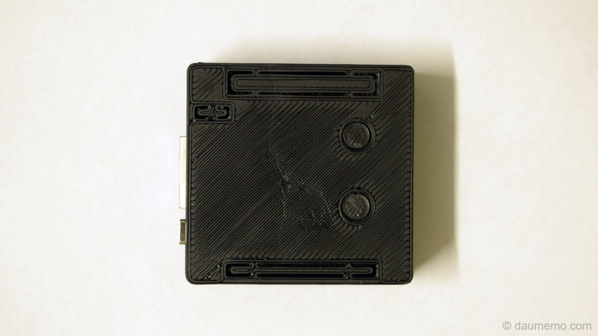
The 3D printed case
Now we have working buttons, but we still need some kind of case for the board and buttons. So, I have designed and 3D printed case for this purpose which can be seen below.

The case is actually a very simple. It has no vents for cooling, but as the board most of the time idles, it doesn’t cause any problems.
You can download the files for 3D printing from my Thingiverse page. Also, I will leave the link at the end of this post.

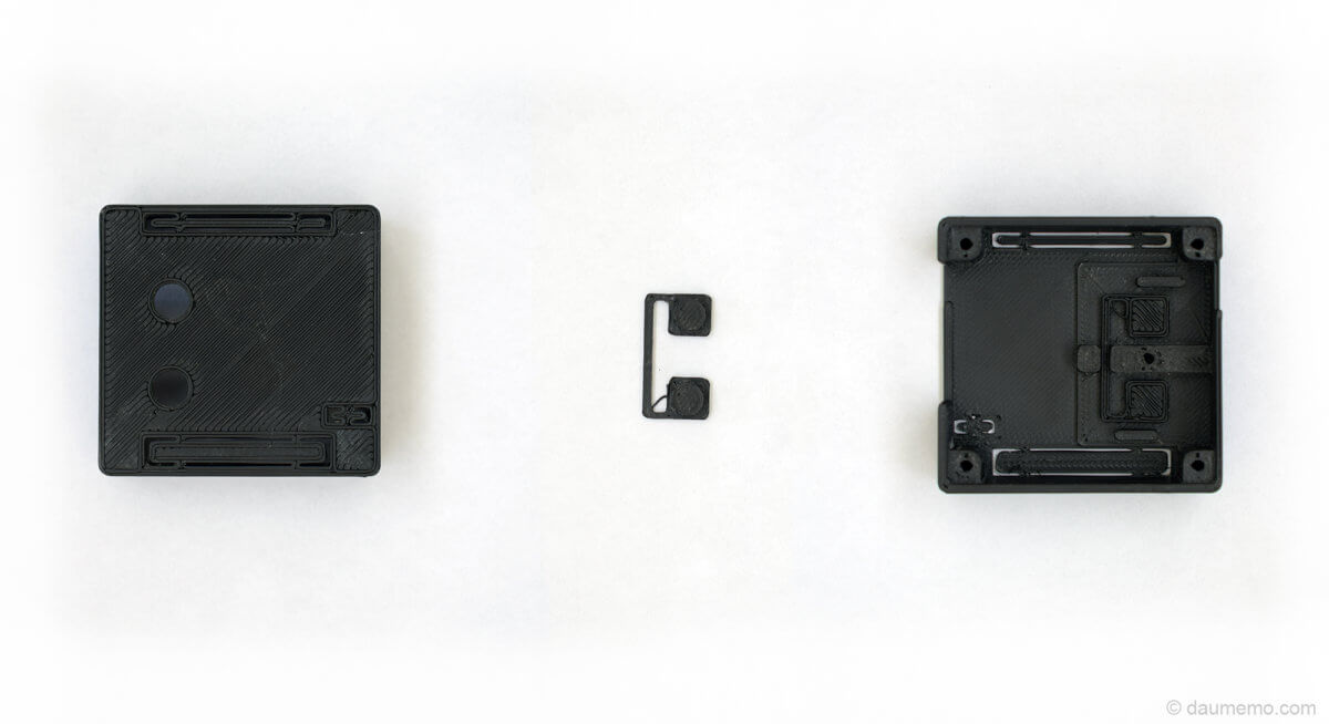
First step is of course to print the needed parts. After doing that, you might need to drill holes with 2.5 mm drill bit and the tap the holes with an M3 tap. You could also use screws instead of bolts with correct size – then you won’t need the M3 threads. There are 5 holes total. 4 of them are used to connect top and bottom parts together. The last one is on the inside of the top part – it is used to screw down the PCB with push-buttons.
The PCB with two buttons
The PCB for two buttons can be made by hand by cutting needed size PCB with knife cut traces:

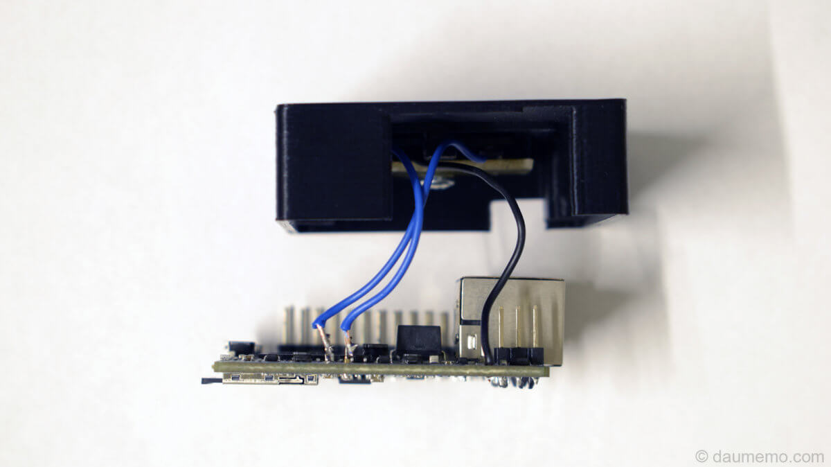
After making such PCB, you will need to solder two buttons with some wires. As you can see, I have used buttons with 2.5mm height. It is possible to use higher buttons, but you will have to add washers to rise the board a bit. The boars should be screwed with a M3 bolt and don’t forget that before that you need to place 3D printed buttons to the top case part.

I personally have just soldered three wire from buttons directly to OrangePi PCB. Two wires went to GPIOs and one to the GND.
After that, whole case can be put together and screwed with four M3 bolts. With such fully closed case, the CPU (while idling) gets to 45 degrees of Celsius.

Summary
So, this was the last part about the OrangePi zero used as OctoPrint server with a small case and two buttons for restarting or powering down the board.
Links
First part: HERE
Thingiverse (files for 3D printing): HERE
Gallery