Handful of older generation AVR MCUs needs ISP (In System Programming) connector to flash your own firmware. Usually if you design your own PCB, you will place somewhere 6 pin header (2×3 pins) as ISP connection. Most of the time it makes sense, unless PCB needs to be small especially in its height. In these situations, it is useful to use a pogo connection.

What are pogo pins? As you can see in photo, pogo pin is spring loaded pin of which one part is soldered to a PCB and the other part (which moves a bit as it is connected to a spring) makes a connection to a flat metallic surface.
There were some circumstances, that a PCB needs to be as thin as possible (including thickness of the PCB and components height). So, in such occasions I use my self-made pogo ISP connector. Upsides of such connection are: there is no additional height to a PCB, there is no need of soldering an extra header, so the PCB looks nicer than one with physical header soldered in. There is one downside – the connection is quite flimsy, so it is easy to accidentally disconnect a connected device.
The PCB was made by me at home. I have written a tutorial how it can be done either etching with chemicals or with a CNC router.
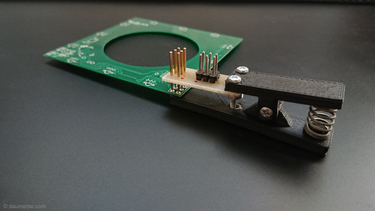
You can see an adapter shown in the photos for replacing a regular ISP to the one with pogo pins. On one end of the adapter you can see six pogo pins which connect to a board. Those pins are also connected to a regular six pin header used for connecting a standard 2×3 IDC connector – to this header one connects ISP programmer. Whole PCB with pogo pins is screwed to a 3D printed holder-clip which clips onto a targets PCB. Such adapter makes it easy to connect it to a board, program a MCU and disconnect the adapter from the board. As I have mentioned, such solution is handy working with space restricted PCBs.

The links for the project files on my GitHub and Thingiverse are below:
https://github.com/daumemo/avr-isp-pogo
https://www.thingiverse.com/thing:3703197