There is not a lot of information on the internet on how to start programming DSP for your DIY audio needs. I will try to show, in my opinion, the easiest and probably one of the cheapest DSP programming setups for a fast start.
Table of contents
- Parts list
- Software list
- How to install SigmaStudio
- Installing freeUSBi driver
- How to install REW
- Connecting DSP with programming board
- First simple DSP program – toggle LED
- Second program – volume control
- Third program – audio low pass filter
- Writing your program to EEPROM
- LINKS
Parts list
A total minimum to get started with a DSP (with affiliate links):
- CY7C68013A Mini Board (Aliexpress)
- ADAU1701/1401 DSP mini development board (Aliexpress)
- USB-A -> mini USB cable
- 2x 3.5 mm stereo jack cables with stripped down one end (for connecting PC mic/output to DSP board)
Software list
All used software is free:
- SigmaStudio – used to graphically create a program for the DSP
- freeUSBi driver – to use the CY7C68013A Mini Board as a DSP programmer
- REW – used to generate a signal on the PC output and record (see as a spectrum) the result on the PC’s microphone/line input
How to install Sigma Studio
Download SigmaStudio Installer from the Analog Devices webpage.
Run the downloaded exe file. The installer will start:

On the first installer’s screen just press NEXT.

Then read the license agreement, click on “I accept…” and press NEXT.

Change install location or use default one and press NEXT. Also, note the installation location – it will be needed in drivers installation steps.
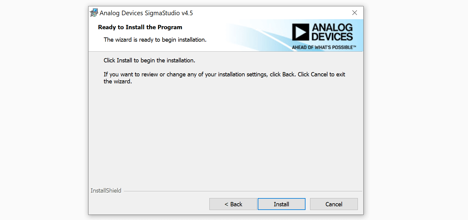
Press INSTALL to begin installation.
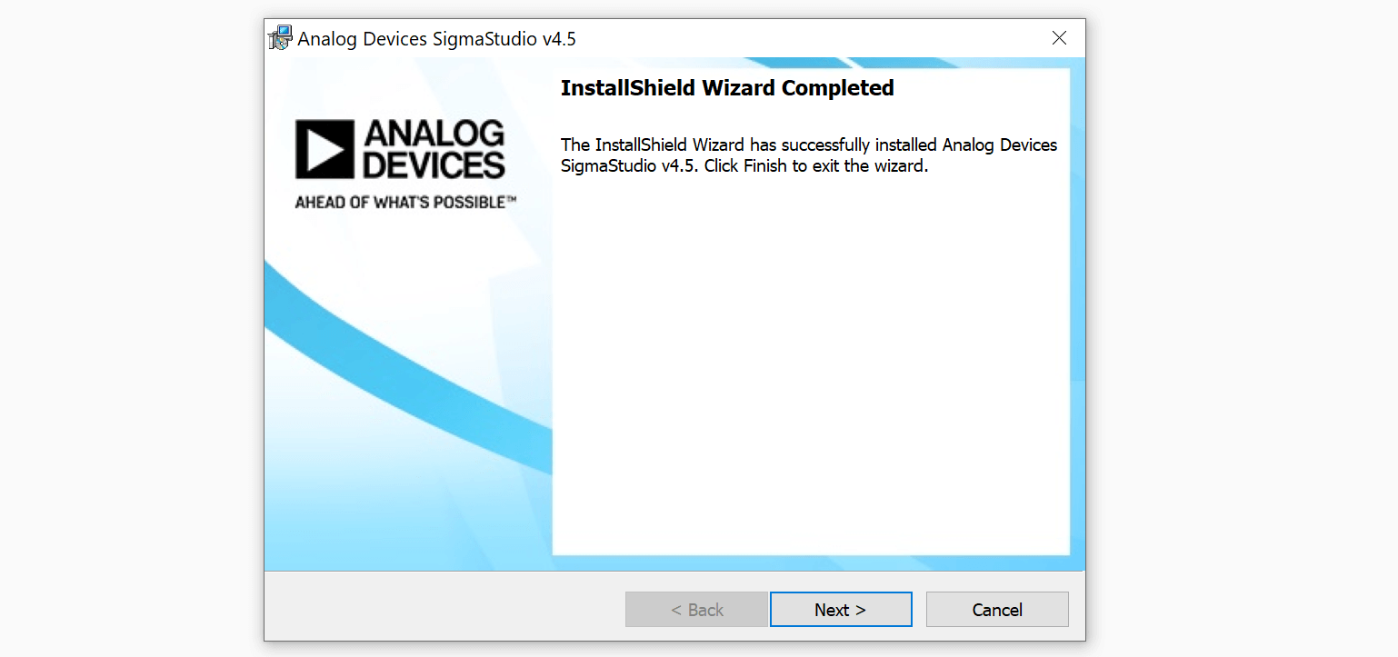
After installation click NEXT to finish the installation.
How to install freeUSBi driver
freeDSP site has a great document on how to use CY7C68013A mini board instead of the original Analog Devices USBi programmer. In that link, an additional adapter board was used, but I am going to use only the CY7C68013A board itself.
After Sigma Studio installation, connect the CY7C68013A board to your PC via USB cable (do not connect DSP board at this moment). Your PC shouldn’t recognize the connected device. So, you will have to install the driver manually.
Next steps are taken from the freeUSBi installation manual. There is information for different types of OS’es, here I will only talk on how to install it on Windows 10.
- Firstly, download driver files as a zip archive from here (click on green code button and select Download ZIP)
- Extract downloaded file. Inside the extracted folder find a needed driver folder for your OS. In my case it was SOURCES\DRIVERS\Win10\x64 folder. You can copy it out to an easily accessible location (for e.g. Desktop).
- Go to the SigmaStudio installation directory (e.g. C:\Program Files\Analog Devices\SigmaStudio 4.5) and go to “USB drivers” then “x64” folder (might be x86 folder if you are using 32 bit Windows version). Copy an ADI_USBi.spt file to your driver folder which you found in previous step.
- Then, go to the Device Manager by right clicking on Windows icon and selecting Device Manager.
- You should see an unknown device in the devices list. Right-click on it and select Update Driver. Then select folder from your PC – choose the same folder where you have copied the “ADI_USBi.spt” file to.
- Because I am using Windows 10, I got a problem while installing the driver (shown below).

To install the driver correctly, you will have to disable signature verification. Do as follows:
- Open settings (type in “settings” in windows search).
- Click on “Update & Security”.
- After that, on the left side of the window press “Recovery”.
- Under the “Advanced startup” text there will be a button “Restart now”. Press on it, and your PC will restart.
- After restart a blue screen with selection will be shown. Select “Troubleshoot”.
- Then press on “Advanced options”.
- Select “Startup settings”.
- Finally, press “Restart”.
- After restart you will be shown blue screen again. Press F7 to disable driver signature enforcement. The PC will restart again.
- When your PC boots up, go to the Device Manager by right clicking on Windows icon and selecting Device Manager.
- As previously, you should see an unknown device in the devices list. Right-click on it and select Update Driver. Then select folder from your PC – choose the same folder where you have copied the “ADI_USBi.spt” file to.
- Now the driver should install without problems. You should now find Analog Devices USBi device in the Device Manager as shown below:

How to install REW
Although you could choose other software for DSP measurements, but I will write about my preferred choice – REW. This software will allow you to generate a signal on your PC’s audio output and measure how DSP changes that signal on its output and on your PC’s audio (line-in/mic) input.
So, first of all, download installer from here.
When download finishes, run the downloaded executable.

On the first installer screen press NEXT.

Then, read the license agreement, select “I accept the agreement” and press NEXT.
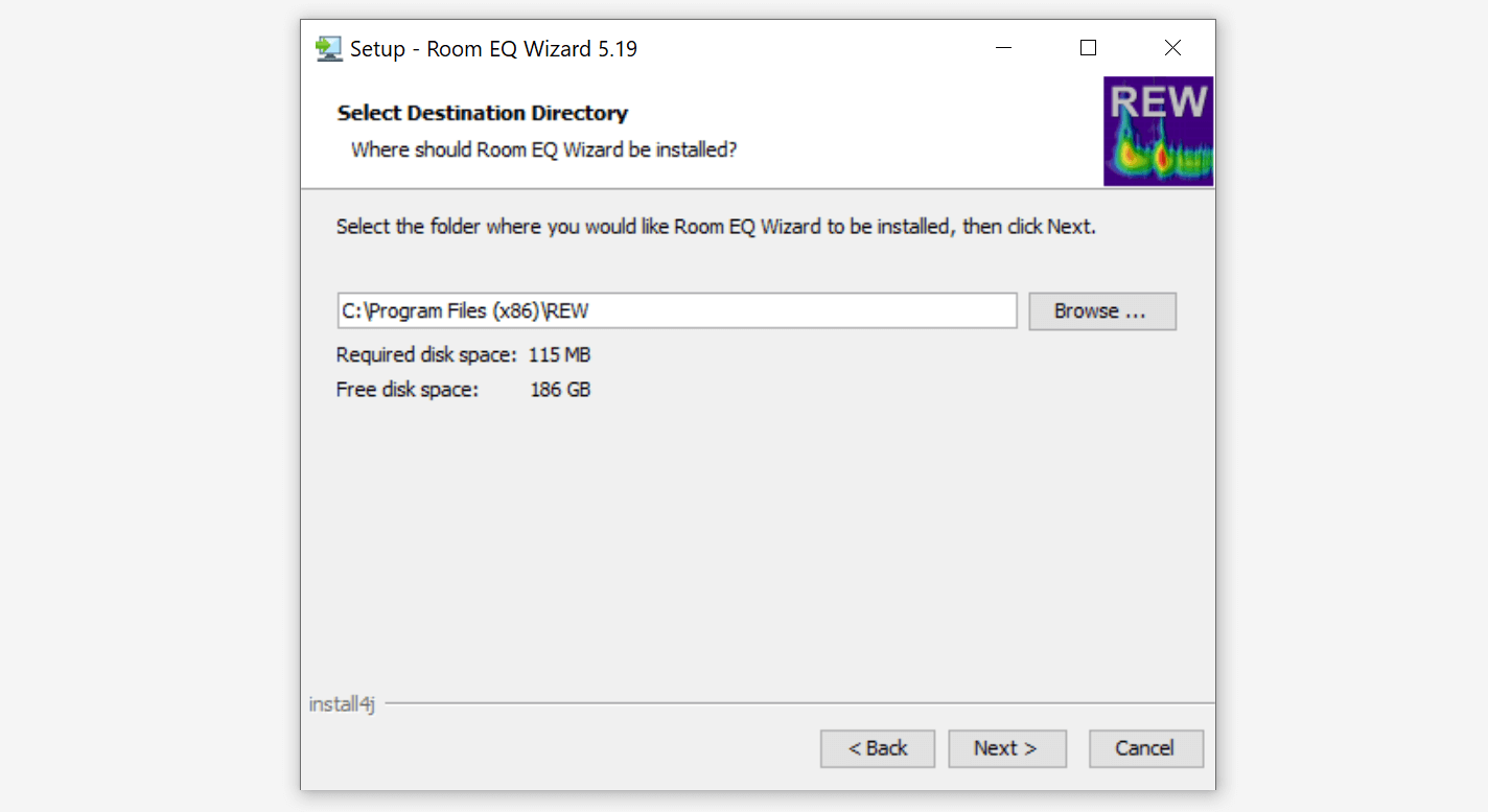
Use default or change install directory and press NEXT.

Select (or unselect) if you want (or not) to create Start Menu Folder and shortcuts for all users. Then, press NEXT.
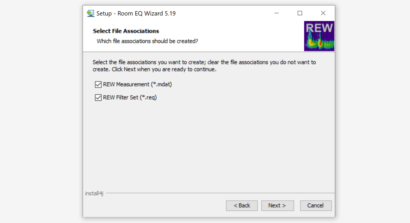
Leave file associations in default selections (all ticked), press NEXT.
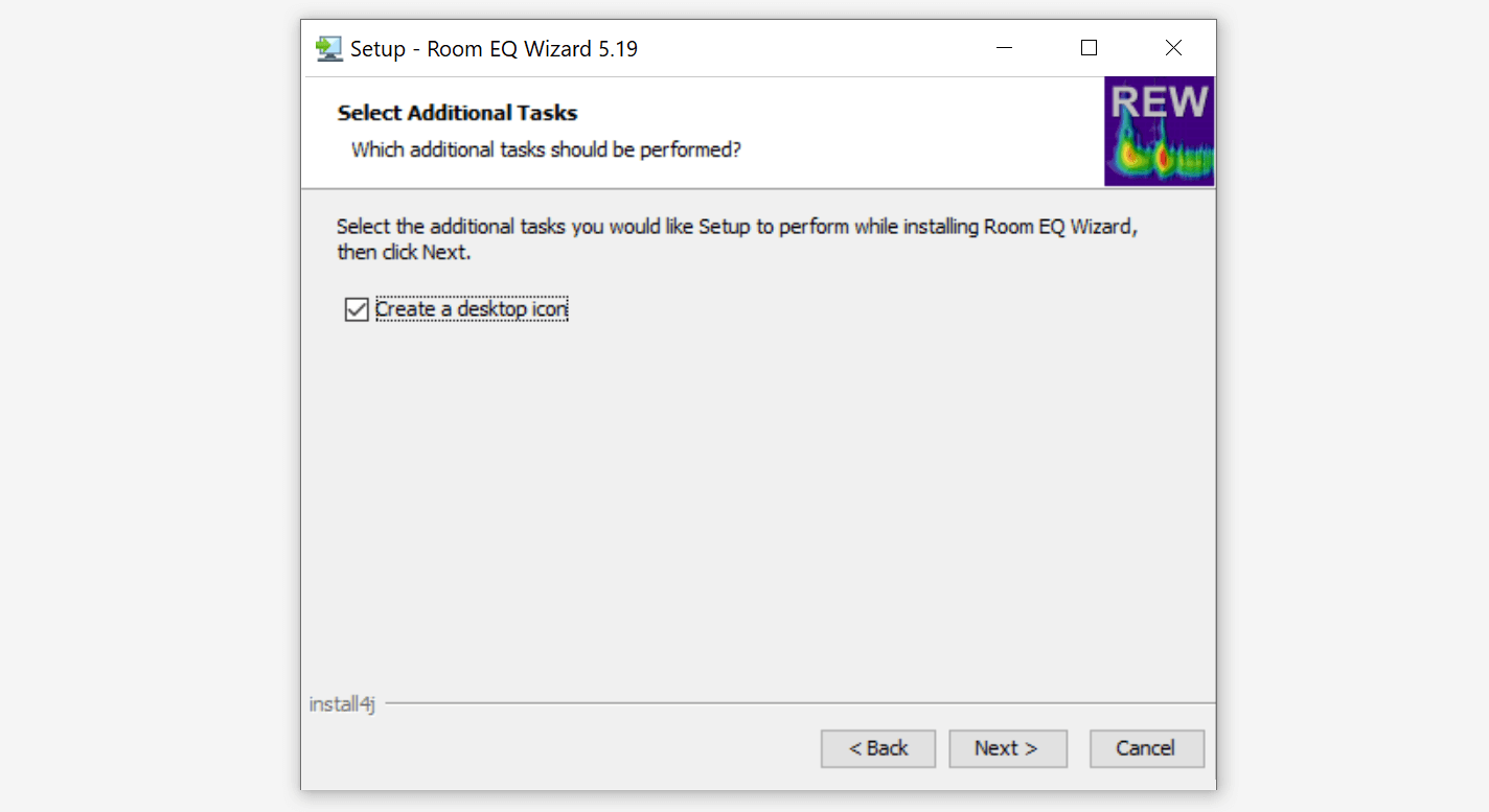
Select (unselect) to create (or not) REW icon on the desktop. Press NEXT.
Installation will start.
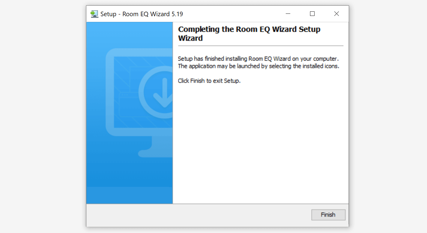
After successful installation press FINISH to exit setup.
How to connect DSP with programming board
First of all, you will have modify CY7C68013A board as shown below, because it does not have any 5V pin on its headers:

After that, you should be able to connect two boards together as follows:
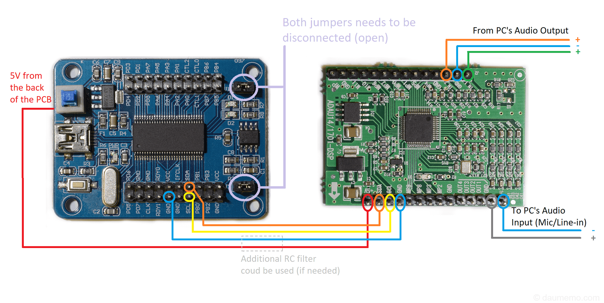
The connection is straight forward. Note, that connection schematic shows both jumpers shorted, but in reality they need to be open (as the schematic text tells you).
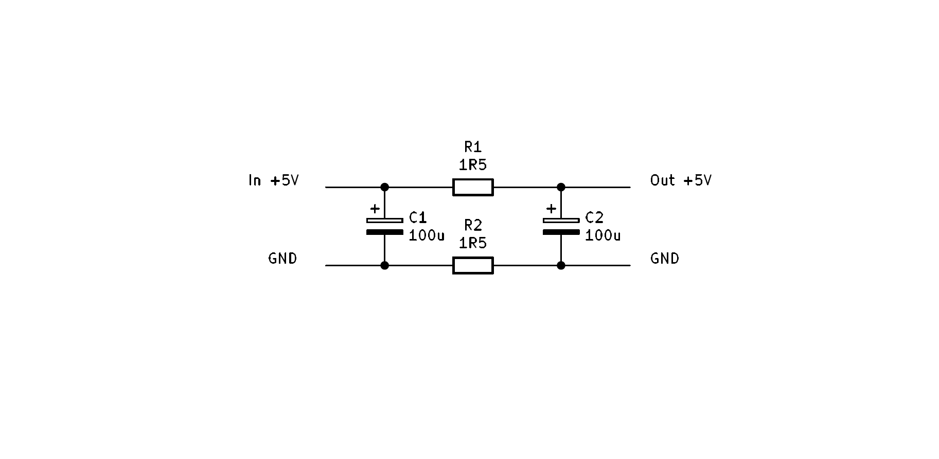
Also, the schematic shows “Additional RC filter” block on the power wires. I had some problems with noisy USB – there were some high frequency (10-20 kHz) spikes in audio spectrum which were audible. So, I have managed to lower them significantly with additional filter:
Also, there might be some problems with finding schematics for both, DSP and CY7C68013A, boards. So, here are schematics which were based on some versions found on the internet and the real board inspection:

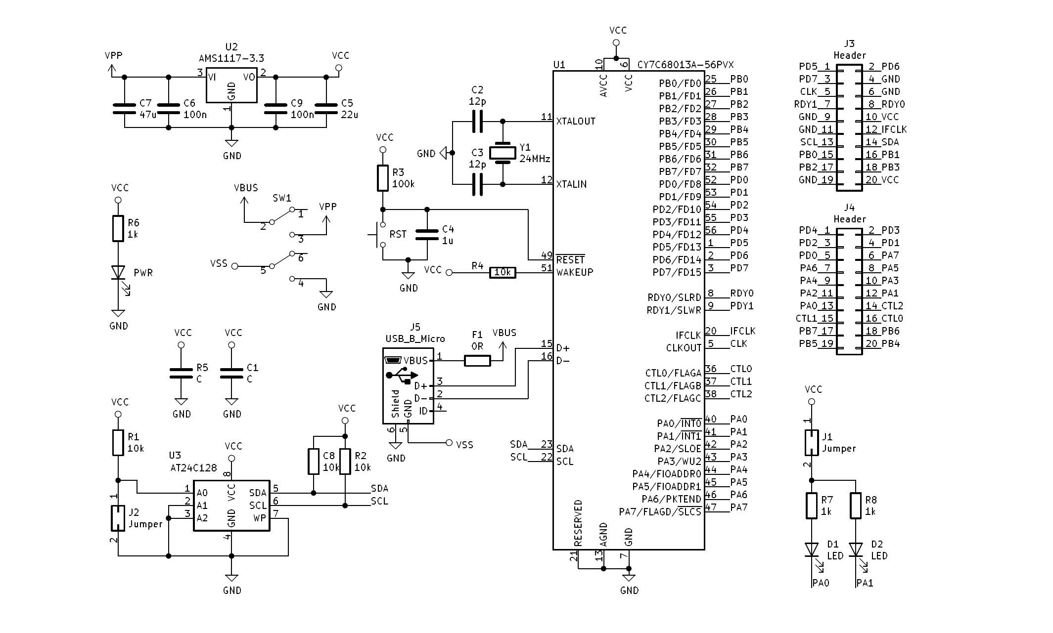
Have in mind, that those might have some mistakes as they are not original (made by vendor), but drawn by me.
Finally, here is a photo, how everything looks connected in reality:

First simple DSP program – toggle LED
The simplest thing to do with the DSP board is to blink an LED which is located on the board. This solution requires only the programmer with the DSP board connected to the PC’s USB port and SigmaStudio installed and running. For this part you won’t need any audio sources etc.
Firstly, start SigmaStudio.
Select “File” -> “New Project”.
Take from the left side of the screen USBi device and drag it to “Hardware configuration” tab, do the same with ADAU1401 and E2Prom devices. Then connect them together as shown in the picture below:

You can see that USB at the moment is red, because the programmer is not connected to the PC. Plug in the programmer with the DSP board to the PC’s USB port and the USB should change its color to green.
Now press on the “IC 1 -170x/140x Register Control” tab, you should see a window like this:

Find MP2 GPIO setting and change it from “Input GPIO Debounce” to “Output GPIO”.
Now go to the “Schematic” tab which is next to the “Hardware Configuration” tab.
Here, on the left, in “Tree ToolBox” you will have different DSP algorithms that can be used in your program (schematic).
Find a GPIO output (IO -> GPIO -> General Purpose Output) and a switch (Sources -> Switch -> 28_0 Format -> On/Off Switch). Place them, select on the GPIO “GPIO_2” and connect as shown in the schematic:

Now click “Link Compile Download” button in the top toolbar. Your program will be loaded into the DSP.
SigmaStudio should show “Active: Downloaded” in the bottom right corner.
Clicking on the button in the SigmaStudio’s schematic should change the LED status in real time.
Also, this project file is available here.
Second program – volume control
Let’s try to do something more useful with the DSP – to control audio volume.
Hardware configuration is the same as in the previous program:
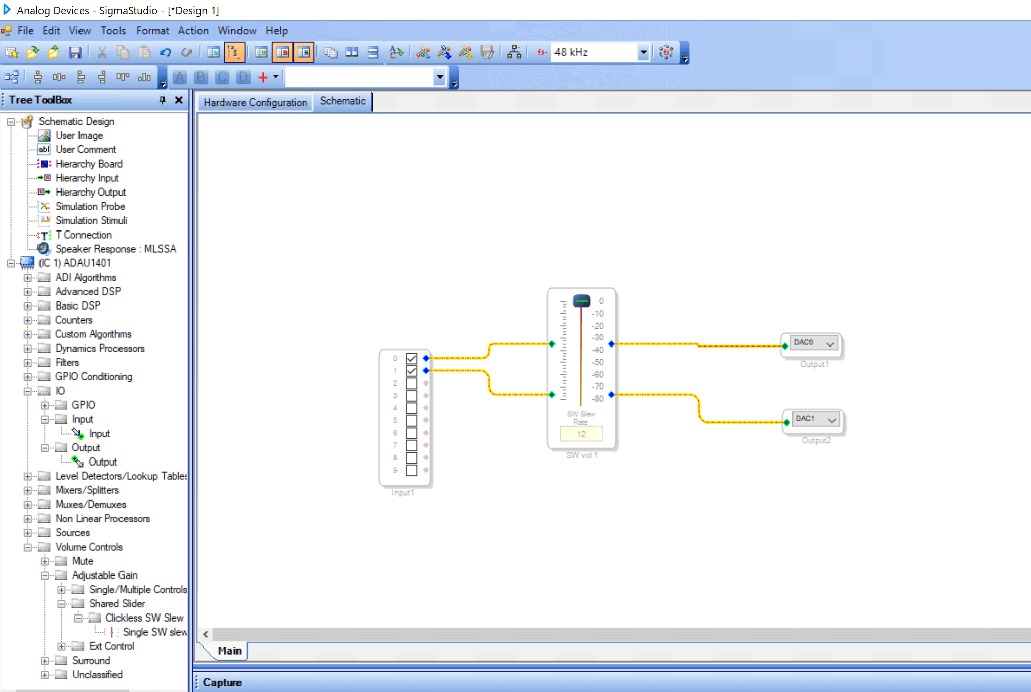
Open “Schematic” tab. Find an input (IO -> Input), two outputs (IO -> Output), a volume control (Volume Controls -> Adjustable Gain -> Single/Multiple Controls ->No Slew -> Single). Drag and drop them into schematic window, right click on volume control’s name, select Add Algorithm -> IC 1 -> Gain. Now instead of one channel volume control will have two channels controlled by the same slider. Finally, connect everything together as shown below:
Now click “Link Compile Download” button in the top toolbar. Your program will be loaded into the DSP. At this point do not close the SigmaStudio and keep it open during next steps.
Also, this project file is available here.
Check the result
Next, if you haven’t connected DSP’s inputs and outputs to the PC’s audio out and mic in, you should do that. After that, we want to see the result of our program. To do that, start REW and when it loads click on Generator and RTA buttons.
On the RTA window press start/stop RTA button (red “record” button on top left). It will start showing real time spectrum of the PC’s input signal. Now run the generator by pressing green triangle and you should see that RTA changes its form – now it shows 1 kHz signal as shown below in the picture:

If you get this result – everything works as expected, if not, you can check if audio in/out is correctly connected to the PC’s in/out jacks. Also, you can check “Preferences” window and try to change some input/output sources there.
Now open the SigmaStudio again and try to change volume sliders position. After that, check the RTA window in the REW – the signal now should be lower (or higher) than before. So it means, that you can not only write a static program to the DSP, but also change some parameters (like a volume value) in real time without rewriting the program.
If, for some reason, while moving the volume slider in the SigmaStudio real signal’s value (in the RTA) does not change, try to reupload (by pressing “Link Compile Download button”) the program again, because sometimes SigmaStudio simply loses connection to the DSP.
Third DSP program – audio low pass filter
The last program is going to be a simple low pass filter.
The connection is similar to the volume control schematic, just instead the volume control slider the filter is used. You can find it in Tree ToolBox: Filters -> Second Order -> Double Precision -> General (2nd order). Place it in the schematic window. Right click on its name. select Add Algorithm -> IC 1 -> 1 channel – Double Precision. Now, instead of one filtering channel we will have two.
Press on the little square icon on the filter which will open a settings window:

Then, change settings as shown above – change to Butterworth/Bessel filter and set it to Butterworth Low Pass. Close the settings window.
Connect everything as shown below:

Click “Link Compile Download” button in the top toolbar. The program should be uploaded to the DSP.
Also, this project file is available here.
Now open REW and press “Measure” button. A window will open:

Before any measurement, you can press “Check levels” button. You should see a similar view:

If it will show that “Level is OK”, you can press “measure”. If you get a message that the level is too low (too high), you can try to change volume level on your windows volume settings and try again to check the level. Even if you get bad sound level indication, you could still try to measure the DSP program’s result.
So, after pressing “Measure”, you should get something similar to:

Of course, there a lots of different filter types in the DSP filter settings, so you can try to play around and see how the result changes with different filter types.
Writing your program to EEPROM
Up to now, every program that we have written was downloaded directly to the DSP’s memory. This memory is overwritten with the contents from the EEPROM each time the DSP is powered up. This happens because by default DSP is configured with self-boot option in this development board. So, all programs which were sent directly to the DSP were deleted on the next startup.
If you want to save the program to the EEPROM, do following steps:
Firstly, after creating you program, write it to DSP via “Link Compile Download” button.
After that, ground WP pin which is on the DSP development board pin header. To do that, just connect WP pin with a jumper or a peace of wire to GND pin. WP pin is write-protect pin for EEPROM. When it is in High status, EEPROM is write-protected.
Then, go to “Hardware Configuration” tab and right-click on ADAU1401. You should see similar view:

Finally click “Write Latest Compilation to E2PROM”. In newly opened settings window leave everything in default values and press “OK”.
Now your program will be uploaded to the EEPROM and it will be always loaded during DSP’s startup.
LINKS
Next part of the DSP tutorial: How to control DSP (volume) with external hardware or MCU.