This time let us talk about one Sigma DSP (ADAU1401) function – volume control, realized in various ways. From previous part about DSP programming we already know that it is possible to control DSP’s output volume directly from the Sigma Studio’s graphical interface. Of course, this is not a convenient solution, because you will need to keep the DSP always connected to your PC. There are other, more standalone solutions, how the volume control can be implemented which is this post’s main topic. Although I will talk about volume, the idea of this post is to cover different ways of interaction with the DSP.
Table of contents
- Parts list
- Software volume control from within Sigma Studio
- External volume control
- Control from an external MCU with I2C
- Summary
- Links
Parts list
Hardware:
- ADAU1401 development board (could be any Sigma DSP) (Aliexpress)
- DSP programmer. Cheap solution was covered previously.
- Some buttons (Aliexpress)
- Rotary encoder (Aliexpress)
- Potentiometer (Aliexpress)
- A PC with needed software installed (read below)
- Some wires and cables for hardware connections.
Software:
- SigmaStudio
- REW (or similar software capable of generating and analyzing audio signals)
Software volume from Sigma Studio
First of all, let’s remember previous volume control circuit:

This one is straight forward – upload it to the DSP and you will be able to control volume through the same Sigma Studio’s GUI. How to get started and upload such volume control example I have already covered in the first part of DSPs tutorial/post.
As I have already mentioned, this is not very practical long-term solution, because it requires to have a PC always connected to the DSP.
External hardware control
When you want to have a truly stand-alone DSP device, there are several different ways, how you can do that. The first one is using external buttons connected to the DSP’s GPIOs. The second solution – you can connect a rotary encoder to the DSP. Finally it is possible to connect even a potentiometer to the DSP.
Changing volume with buttons
An example schematic, how some buttons can be connected to the DSP (in this case ADAU1401) is shown below:

Each GPIO has an internal pull-up resistor, so the button pins must be connected between the GPIO and GND. Of course, you will need to program the DSP with a schematic which will use those buttons to do actual volume change:

The control block, from a first glance, has more input/output pins that it needs. There are regular audio in/out pins and two inputs for the buttons. Furthermore, there are two “interface” in/out pins. These pins connect to an interface register. In this case it is interface register 0. This register is used to save the volume value into the EEPROM during power down. After power-up the DSP loads again the last volume value. There are eight interface registers, so up to eight parameter values could be saved automatically to the EEPROM.
The checkbox “Invert GPIO”, as I have tested out, inverts those two buttons. So, if the first button increased the volume value, after inversion, it will decrease the volume. The same applies to the second button.
Parameter “Hold (ms)” defines how long the current volume level is kept before the repeat pulses are generated to increase/decrease the volume while the button is pressed.
“Repeat (ms)” defines the time interval between repeated pulses during the long button press.
Parameter “SW Slew Rate” controls the slew ramp speed for the volume transition between following volume table points.
The volume control block also has volume value table. This table consist of an array of values which corresponds to steps-volume pairs. It is up to you to define how the volume will be changed (linear, logarithmic, …). Mine values were: [1, 0.5, 0.25, 0.12, 0.06, 0.03, 0.01, 0.005, 0.0025, 0.001]. Also, the number above the “Table” button defines how many values there are in the volume value table.
After connecting the HW schematic and loading the DSP program, a short press of a button will change volume in one step, while long press changes the volume continuously – as long it is pressed.
DSP volume control with a rotary encoder
Similarly, you can change volume with a rotary encoder. The hardware connection is shown below:
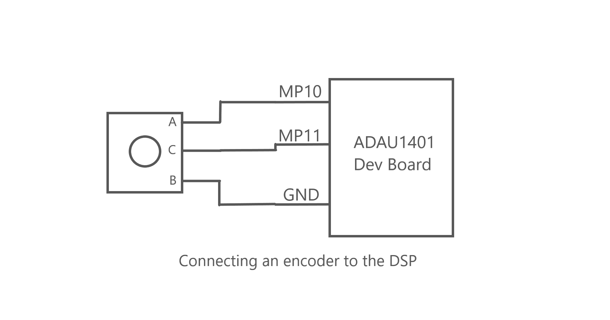
And here is the Sigma Studio’s schematic:
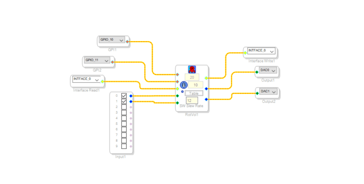
Encoder’s block is a bit simpler than the button block. It has the same input/output pins. Only this time instead of two buttons, you will need to connect the encoder pins.
Also, it has a “Debounce” value. It is counter based delay to let the pin value to settle on one value.
Like the button volume control, it has a volume value table and a “SW Slew Rate”. Values in the table are the same as in the button control: [1, 0.5, 0.25, 0.12, 0.06, 0.03, 0.01, 0.005, 0.0025, 0.001].
After uploading the program to the DSP, the encoder turns will change the DSP’s output volume.
Also, one thing to notice – when using the encoder block, you will need to set “Input GPIO No Debounce” instead of “Input GPIO Debounce” in hardware configuration tab. This is needed to get correct encoder’s behavior. If you won’t change the setting, the DSP will lose steps during fast encoder’s shaft rotation.
Changing volume with a potentiometer
Obviously, a potentiometer can be used to change the audio volume. In analog audio this is done with a directly connected potentiometer to the audio path. But it can be done differently than that when there is a DSP.
We can connect the potentiometer like it is shown below:

In this case potentiometer is used to change the voltage on the ADC pin, which is number 9. The potentiometer resistance is 2 kOhm. Also, DSP’s pin configuration should be changed as follows:

As you can see, MP9 is set to ADC0. Now, we can create a schematic for the DSP’s program:

Here we are using “Single slew ext vol” block, which changes the volume according to external input value. This value is going to be the ADC0 readings.
After loading the program to the DSP, by turning the potentiometer knob you will change the audio volume. Unlike with analog audio, now the volume is changed inside the DSP and not directly via potentiometer.
Another great schematic block is called “DSP Readback” which allows to show inside the Sigma Studio GUI what some real parameter values are inside the DSP. Let’s make an example schematic by editing the same volume control via potentiometer:
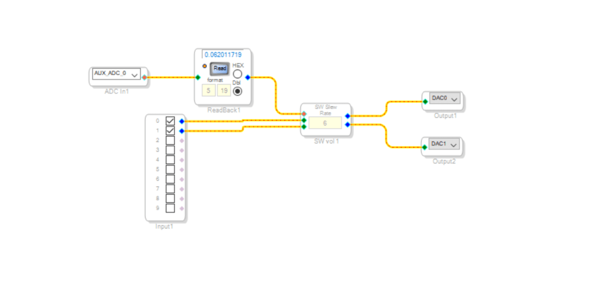
Now, the readback block will show the value which comes from the ADC0. In this case the value range is from 0 to 1. Keep in mind that in reality voltage on the ADC changes from 0 to DSP’s VCC voltage. Also, in theory ADC value has to be in the range [0…1], but in reality, you might never get the perfect 0 or 1 values because of a slight voltage drift from the power rails on the ADC pin, or of the ADC’s readout error.
Control DSP volume from an external MCU
The last topic is how to control the DSP from your Arduino. First of all we need to inspect, where the data is written to. Let’s again create the simple volume control schematic:
Now, “Link Compile Download” program to the DSP and inspect the Sigma Studio’s capture window which is located on the bottom of the screen:

Here you can already see that “Param” to address 0x00 first 4 bytes are 0x00, 0x80, 0x00 and 0x00. Which in 5.23 format means “1” (unity gain). To make it more clear move the volume slider down and now you will see exact channel 0 and channel 1 values being written:
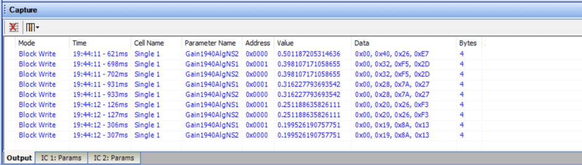
One channel’s volume value is in the address 0x00 and the other channel’s – in the 0x01 address. So, now it should be clear that to change the volume, we need to write to 0x00 and 0x01 addresses four bytes of data each. To do that, let’s write a simple Arduino program:
#include <Arduino.h>

#include <Wire.h>

#define PIN_SDA 4 //D2
#define PIN_SCL 5 //D1

uint32_t data = 0x800000;

void setup() {
  Wire.begin(PIN_SDA, PIN_SCL); //could be just Wire.begin() if defaults are used.
  Serial.begin(9600);
}

void loop() {
  if (data <= 1) data = 0x800000; // reset if we have the lowest value;

  Wire.beginTransmission(0x68>>1); //0x68 - DSP's (ADAU1401) I2C address, lib adds additional 0 at the end.

  Wire.write(byte(0x00));//pot addr H1
  Wire.write(byte(0x00));//pot addr L1

  Wire.write(byte(0x00));//value byte 0;
  Wire.write(byte(data>>16)&0xff);//value byte 1;
  Wire.write(byte((data>>8)&0xff));//value byte 2;
  Wire.write(data&0xff);//value byte 3;

  Wire.endTransmission();

  Serial.println(String((data>>16)&0xff) + " " + byte((data>>8)&0xff) + " " + String(data&0xff));

  data /= 2;

  delay(500);
}
This code was written for ESP8266, but it should be adaptable to all processors which runs Arduino.
So, because the MCU was connected to the DSP with I2C, the “Wire” library was used. There is also only one variable “data” which holds volume value. Initial volume is 0x800000 which in 5.23 format mean “1”. This format means that 5 bits are used for integer part (left number side from the decimal point) and 23 for fractional part (right side from the decimal point). So, the value 0x800000 could be seen as (0x1).(0x0) . We just need to reduce this number to lower the volume, so everything below 0x800000 will reduce the output signal.
The main part of the code is in the loop() function. Here we write the data to the DSP. Firstly go two bytes of the parameter register address. In this case it is 0x0000 – so the data is written to the first channel only. After that, four data bytes are written. First byte is always going to be zero, but the other three are taken from the data variable. Finally, the same data is also written to the serial port.
I still haven’t talked about the schematic, how the MCU is connected to the DSP. So, here is the schematic:
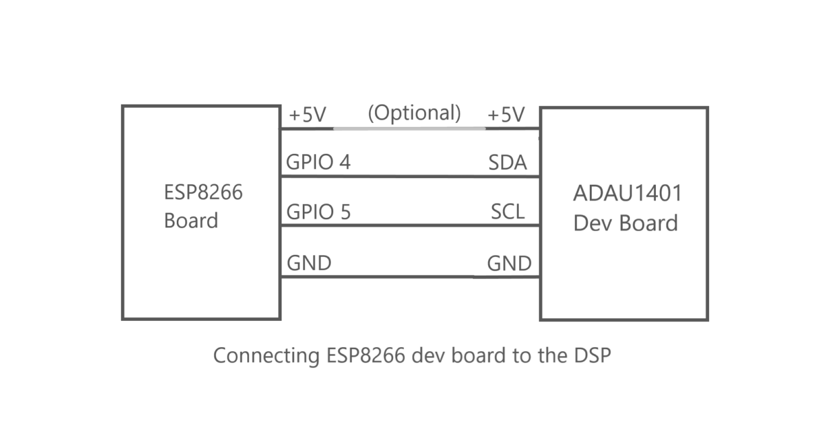
Note, that at this point the DSP program (volume control) should be saved to the DSPs EEPROM, so it will boot with a needed program after you disconnect it from a PC and connect to the MCU.
After connecting MCU to the DSP and writing the program to the MCU you should be able to see volume constantly changing. For signal generation and DSP output inspection REW program could be used. How it can be used I have already written previously.
Of course, this DSP volume control method is not the most convenient, because it covers only parameter control of the DSP. The DSP’s EEPROM still needs to be written with a PC, but later I will cover other means of writing full program to the DSP.
Summary
So, as you can see there are many methods how you can make an interface with a DSP. It can be either stand-alone solutions as buttons, encoders, potentiometers. Or DSP can be controlled from an MCU where your main program with an advanced user interface (for example control through a WEB interface) is written.
LINKS
Previous DSP post: How to program Analog Devices DSP?
Analog devices web-pages on some used volume controls: Button control, Encoder.
Using Hardware Controls with SigmaDSP GPIO Pins.