In this introduction into tinyAVR 0-series devices I am going to talk about where these microcontrollers can be used, what pros and cons they have and why you should or shouldn’t use it in your DIY electronics projects.
Why I am writing about it?
So, first thing first, why I have decided to write about these tiny MCUs? The answer is quite simple – I am thinking of using it for some of my projects, so it would be a great idea to dig deeper into these MCUs possibilities and drawbacks.
Also, such blog posts can become great cheat sheets for me and others, when you need to find the snippet of code or more detailed walkthrough on how to use one or another feature the MCU has.
The third reason, why I have decided to write about tinyAVR 0 series microprocessors, is that these 8-bit MCUs are quite simple in their architecture. Although, they might not have some advanced features, they are good for understanding basics on how to write vanilla code for basically any MCU. So, if you, for example, have already used Arduino boards for your projects, but want to understand what actually happens “behind the hood” – it is good idea to start with ATtiny microcontrollers.
Why tinyAVR 0-series MCUs?
There are many different ATtiny family microcontrollers and a part of them are so called tinyAVR 0-series MCUs.
These are newer generation of ATtiny AVR 8-bit microcontrollers. Their manufacturing started in 2018, so they are quite new in the market. Also, they have newer programming interface, which is called UPDI (Unified Program and Debug Interface) – if you are familiar with programming of older devices, that knowledge (about the interface itself) won’t be applicable in this case.
Probably one of the greatest things is that these microcontrollers are one of the cheapest in the market. Although, not so powerful, they are still useable for simple DIY projects, where you don’t need so many features and CPU power which, in the end, will be never used.
Also, these MCUs might be a way to go if you want to transition from trough-hole component into an SMD world. Most of 0-series ATtiny MCUs are in SO package (SO-8 or SO-14) which have large, still easy to solder, pins. So, you first all-SMD project could be based on a tinyAVR 0-series MCU. If you still need DIP package, you could just use SO to DIP breakout board and install it into a breadboard.
TinyAVR 0-series MCUs
There are handful of 0-series MCUs: ATtiny202, ATtiny204, ATtiny402, ATtiny404, ATtiny406, ATtiny804, ATtiny806, ATtiny807, ATtiny1604, ATtiny1606, ATtiny1607.
Whole overview picture you can see below:

As you can see, these are microcontrollers which have flash range from 2kB to 16kB and pin count from 8 to 24. Also, keep in mind, that devices with different Flash size typically have different SRAM and EEPROM sizes.
One of the greatest things about these microcontrollers is that they have a feature set which is constant across all 0-series devices. So, you don’t have to check every device’s datasheet if one or another feature is available.
0-series MCUs can work up to 20 MHz. Which is more than enough for most non-advanced projects. As already mentioned, they have from 2 to 16 kB of Flash which again, not something grout breaking, but more than enough for basic projects and especially for its price.
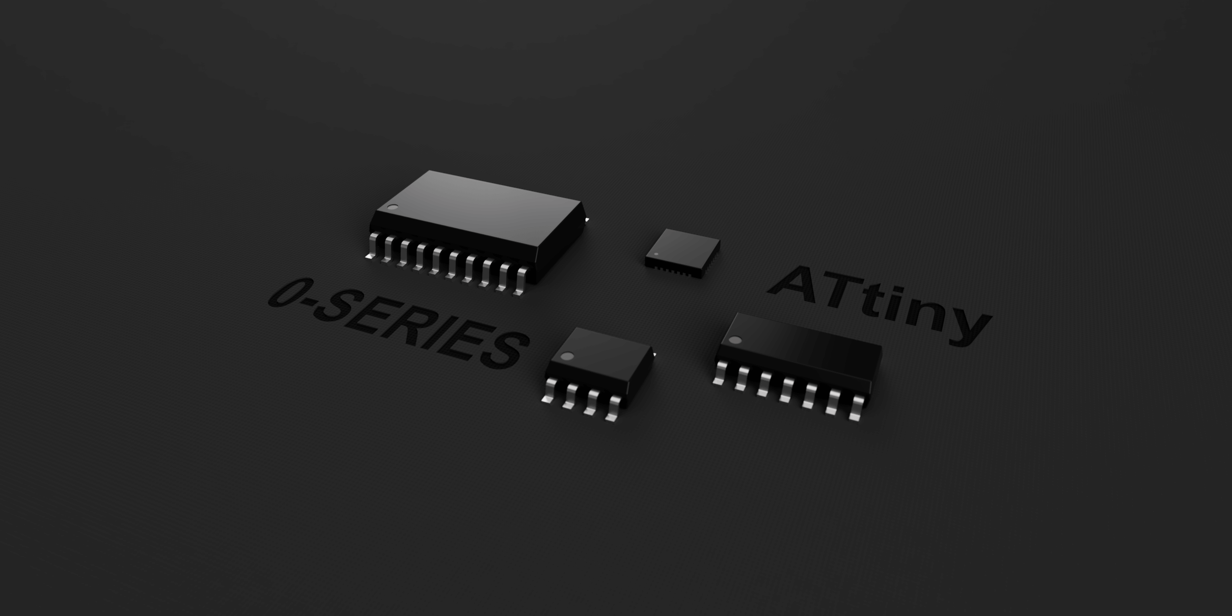
Available IC packages:
- 8-pin SOIC150
- 14-pin SOIC150
- 20-pin SOIC300
- 20-pin VQFN 3×3 mm
- 24-pin VQFN 4×4 mm
Naming scheme
The naming scheme of new ATtiny device’s include flash size, series and pin count as follows:

Speed Grades
- 0-5 MHz @ 1.8V – 5.5V
- 0-10 MHz @ 2.7V – 5.5V
- 0-20 MHz @ 4.5V – 5.5V
TinyAVR-0 peripherals
Most of these MCUs have such peripherals:
- One 16-bit Timer/Counter type A (TCA) with a dedicated period register and three compare channels
- One 16-bit Timer/Counter type B (TCB) with input capture
- One 16-bit Real-Time Counter (RTC) running from an external clock or internal RC oscillator
- Watchdog Timer (WDT) with Window mode, with a separate on-chip oscillator
- One USART with fractional baud rate generator, auto-baud, and start-of-frame detection
- One host/client Serial Peripheral Interface (SPI)
- One Two-Wire Interface (TWI) with dual address match
- Philips I2C compatible
- Standard mode (Sm, 100 kHz)
- Fast mode (Fm, 400 kHz)
- Fast mode plus (Fm+, 1 MHz)
- One Analog Comparator (AC) with a low propagation delay
- One 10-bit 115 ksps Analog-to-Digital Converter (ADC)
- Multiple voltage references (VREF):
- 0.55V
- 1.1V
- 1.5V
- 2.5V
- 4.3V
- Event System (EVSYS) for CPU independent and predictable inter-peripheral signaling
- Configurable Custom Logic (CCL) with two programmable look-up tables
- Automated CRC memory scan
- External interrupt on all general-purpose pins
tinyAVR-0 Pros and Cons VS 1- and 2-series MCUs
Although this post is about 0-series MCUs, you should know that there are also 1- and 2-series ATtiny AVR microcontrollers. The main difference between the series is that 2-series has most features and peripherals of them all, while 0-series being the most stripped-down version of them all.
First of all, 0- and 1- series MCUs don’t have a dedicated RESET pin. It is not something that I would miss out, but it might be important for someone. Also, 0-series has least amount of timer, while 1-series have type D timer and both 1- and 2-series have more of type B timers.
Also, 2-series MCUs have a 12bit differential ADC instead of single ended 10 bit found on 0- and 1-series.
Finally, only 1-series have 8-bit DAC hardware, which is neat feature in some cases.
tinyAVR-0 vs Arduino (8 bit) vs 32 bit
Let’s compare some know solutions in microcontrollers world: tiny 0-series, Arduino board based on an 8-bit mega AVR, and an ARM 32-bit MCU.
Both tinyAVR 0-series and MegaAVR (Arduino) are 8-bit MCUs, working up to 20 MHz. So, they might be limited in situations where real-time math with 32-bit integers needs to be done frequently. In these situations, a real 32-bit MCU will outperform any 8-bit MCU. In addition, 32-bit MCU tends to have a faster clock frequency (usually 40+ MHz, some goes up till 200 MHz).
Also, tiny 0-series MCUs are outperformed by flash, RAM size of the MegaAVR or ARM MCUs. As the target devices using tiny 0-series should be quite simple, you should not feel the lack of available flash size.
Feature and peripheral count could be another drawback of tiny 0-series MCUs. They might just don’t have enough required periphery for some projects and situations out there.
Finally, although it is possible to run Arduino on tiny 0-series device’s, I doubt that it is feasible idea because of possible overhead your code might not fit into the flash.
Programming interface
The tinyAVR 0-series microcontrollers use Unified Program and Debug Interface (UPDI for short). This interface usually has one data pin, which is used to program the MCU, and two power pins, for powering the MCU from an external power supply source.
The connection is done as follows:

As it is one data wire programming interface, it takes small amount on PCB, which is a good thing for projects where size really matters.
One way to program an AVR device with UPDI interface is to use original UPDI programmer made by Microchip. One of the programmers, which can program mentioned AVR MCUs is called ATMEL-ICE. It is universal programming device which supports many different interfaces: JTAG, SWD, PDI, TPI, aWire, SPI, debugWIRE and UPDI. Is seems like great, universal and professional device, but the main problem with it is its price. The programmer costs around 160 USD (at moment of writing). So, it is not really a feasible solution for hobbyists.
Another way to program an UPDI device is to use a self-made programmer. These are based on easily available, cheap hardware. I have already written on how I built one for myself here.

Programming Software
Microchip’s recommended software for programming of AVR MCUs is Microchip Studio (earlier called Atmel Studio). It is an Integrated Development Environment (IDE) for developing and debugging AVR® and SAM microcontroller applications. It is a free tool which you can download from the Microchip’s website. If you are going to use their UPDI programming device, their IDE will work perfectly with it. The inconvenience might arise, if you are going to use a self-made UPDI programming device. In this case the IDE “won’t see” the connected programmer, and you will have to upload your built .hex file into the flash using third party software (like avrdude).
If you are going to use a self-made programmer, I would recommend using PlatformIO IDE for writing the code. Depends on the device used, PlatformIO usually supports programming device’s out-of-the box. So, the workflow is: create new project, write some code, build it and send to connected UPDI device via single button click. Moreover, PlatformIO supports not only AVR or other Microchip’s manufactured MCUs, but it also supports microcontrollers made by other manufacturers like Espressif, Texas Instruments, Nordic Semiconductor and many others.
You can also use Arduino IDE to program tinyAVR devices. I believe there are more IDE available out there which could be used to program microcontrollers, so it is really up to you, what software to use.
What’s next? (Summary)
So, from this post it should be clearer about what kind of devices are tinyAVR 0-series microcontrollers. These are small and cheap devices capable of doing (not so) simple tasks and can be used in many different DIY electronics projects.
The next blog posts will include hands on experience and code examples of using different peripherals and features found on tinyAVR 0-series microcontrollers.
Next series part on how to use tinyAVR GPIO: Attiny (tinyAVR) series-0 and how to use their GPIO
Links
Getting Started with tinyAVR® 0-series
ATtiny202/204/402/404/406 Datasheet
ATtiny804/806/807/1604/1606/1607 Datasheet