If you are interested in DIY electronics, at one point in life you might encounter an Atmel MCU with an UPDI programming interface. The original programmer costs quite a lot, so most obvious solution would be to make one by yourself. So, in this post you will find out what parts and software you will need to make a DIY UPDI USB programmer.
Parts list
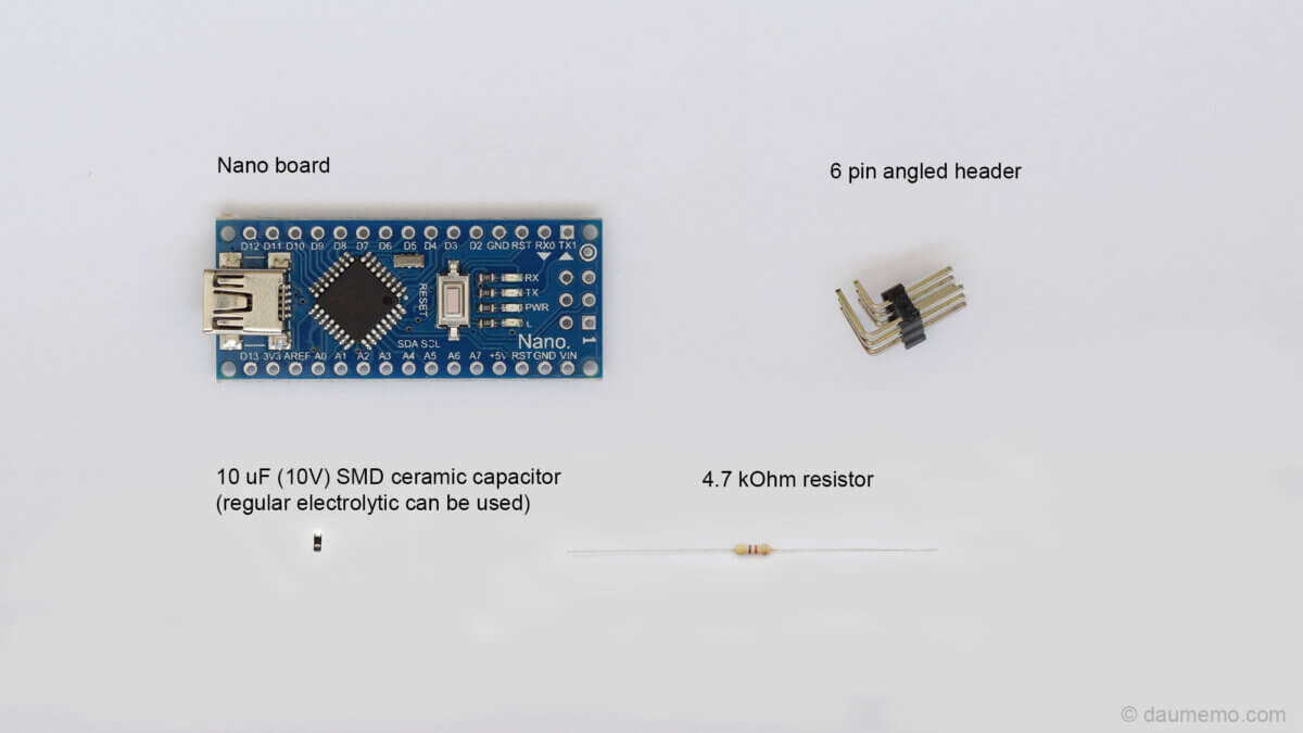
Hardware:
- Arduino Nano or compatible board (Affiliate Aliexpress)
- 4.7 kOhm through-hole resistor (Affiliate Aliexpress)
- SMD 10 uF ceramic or tantalum capacitor, as an alternative, through-hole electrolytic capacitor could be used (Affiliate Aliexpress)
- 6 pin angled header (Affiliate Aliexpress)
Tools:
- Soldering iron, solder, soldering flux
- Wire cutters
- 3D printer (Optional)
- Sand paper (300 and 800 grid) (Optional)
- Super glue (Optional)
Software (not everything is needed):
- Arduino IDE – used for programming UPDI programmer itself
- Avrdude (Avrdudess) – used to program an MCU
- Microchip Studio (previously AVR Studio) – used to write a code
- PlatformIO – an alternative to both, Avrdude and Microchip Studio
- jtag2updi – library/ source files for programmer’s firmware
Uploading firmware into the Nano
First thing what you want to do is to upload needed firmware to the Arduino Nano board.
This part is based on ElTangas jtag2updi library on GitHub.
There you will find out, that it is possible to build the code using avr-gcc or Arduino IDE. I have chosen the second (Arduino IDE) method.
Firstly, download all files via Code -> Download ZIP.
Extract the downloaded zip archive. You should have a folder named jtag2updi-master.
Inside jtag2updi-master there will be folder named source, rename it to jtag2updi.
Now, inside newly renamed jtag2updi folder find jtag2updi.ino file and open it with Arduino IDE. In Arduino IDE check, if the correct board is selected (Tools -> Board).
Connect Arduino Nano or compatible board to your PC and hit Upload button in Arduino IDE. If everything is OK, you will have programmed board, ready to be modified with additional hardware.
Building the UPDI programmer
Now, when you have your board programmed with jtag2updi firmware, next step is to modify the board, so it could actually work as a programming device.
So, here is what parts I have used for the programmer:
First thing to do is to make some modifications to the 6 pin header.
From the connector side, cut off the three bottom pins and from the inside cut the angle of the top middle pin, or just make it straight:
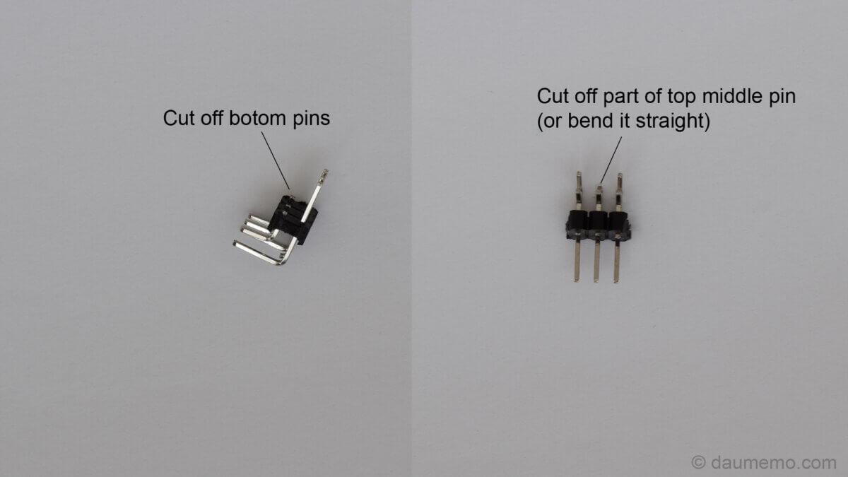
Don’t cut off all top middle pin, leave some of it, so you could solder a resistor to it.
Then solder everything as follows:
Firstly solder in the 6 pin header. Solder only pins, which are shown below:

Then, solder other parts as shown in the picture:
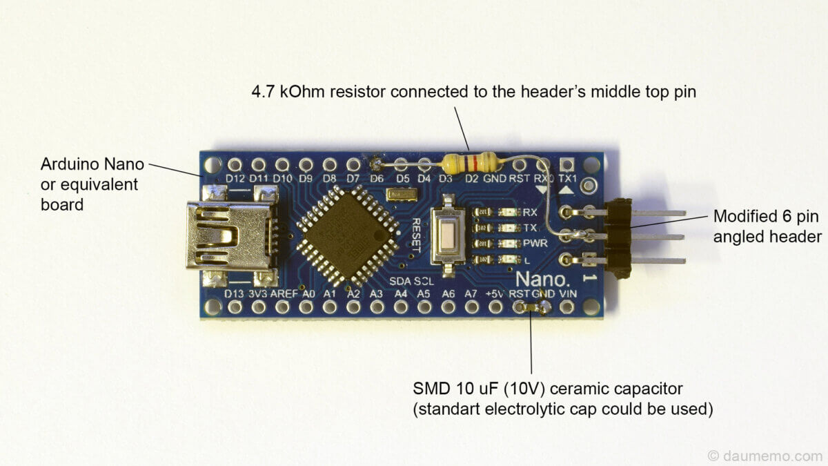
The 4.7 kOhm resistor connects D6 pin with 6pin header’s top middle pin. The 10 uF capacitor connects RST and GND pins.
And that actually all, to make this device act as an UPDI programmer. You can use it as it is, wrap it with heat shrinkable tube, or do as I did and make a 3D printed housing.
3D printed enclosure
I have designed and 3D printed an enclosure with an SLA 3D printer. The whole building process is as follows:
3D print two enclosure parts (download link is at the end of this post):

You can put the board inside and glue the parts together, but I additionally painted on the top part with black spray paint:
After that, I sanded down top side with sanding paper (300 grid and then 800 grid), so only the letters, which are a bit deeper that the enclosures surface were left black:

Assembly
When the enclosure is ready to be assembled, put the Nano board inside the bottom part:

Here you can add some glue on the 6pin header’s top middle pin, so it would not slide in, when you put a connector on it.
Next, add some (super) glue on the board’s and enclosure’s corners and put the top part. And your DIY UPDI programmer is now finished:

Finally, here is a picture of this device’s usage for an Attiny404 MCU programming:
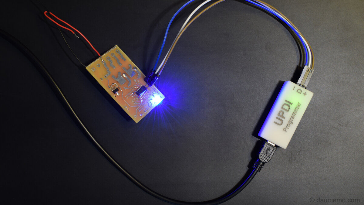
Testing out with Avrdude
For a first test, how the programmer behaves, I had used Microchip studio and AVRDUDESS (GUI for avrdude)
With Microchip Studio I created a new project for Attiny404 MCU and wrote simple code inside main.c:
#include <avr/io.h>

int main(void)
{

	//PA7 is blue LED
	PORTA_DIRSET = (1<<7); //set to output
	PORTA_OUTSET = (1<<7); // set HIGH;

    while (1)
    {

    }
}
Then, press Build -> Build solution and a .hex file will be generated inside the project folder.
This .hex file needs to be uploaded into the MCU, so for this purpose I have used AVRDUDESS.
Before using AVRDUDESS, you will need to modify one file, which is located inside AVRDUDESS installation directory and is called avrdude.conf. Replace this file with an avrdude.conf which is found in the jtag2updi downloaded zip archive.
Then, open AVRDUDESS, select jtag2updi programmer and select .hex file to be uploaded. After that, click program and it should upload the code to the MCU.
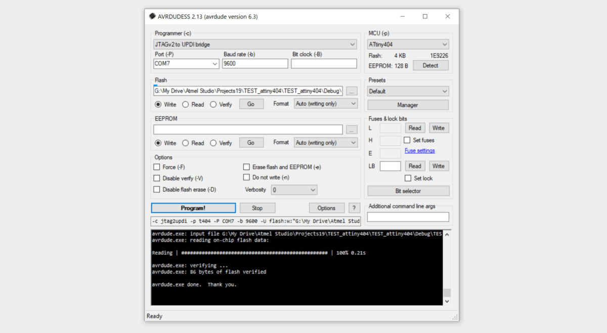
If it does not work, try lowering baud rate and/or selecting correct COM port. Also, I have found out, that for some reason detect function did not wanted to work for me, but still, it programmed the MCU.
Programming an UPDI device using PlatformIO
Actually, even easier is to use PlaformIO to program an Attiny404 or other UPDI MCU. Just open PlatformIO, create a new project with board selected to your MCU (in my case it was Attiny404) and framework set to Arduino. The framework will be deleted in later steps, so the code will use only default manufacturer’s libraries.
When the project is created open main.cpp file (in src folder) and paste in the code:
#include <avr/io.h>

int main(void)
{

	//PA7 is blue LED
	PORTA_DIRSET = (1<<7); //set to output
	PORTA_OUTSET = (1<<7); // set HIGH;

    while (1)
    {

    }
}
Now, open platformio.ini file and delete the framework = … line, so it contains only these lines (which are generated from your board selection and might be different in your case):
[env:ATtiny404]
platform = atmelmegaavr
board = ATtiny404
Then, connect the UPDI programmer with your MCU connected and press upload button. If you are doing it for the first time, the PlatformIO will download needed packages, build and upload the code to your MCU.

Summary
So, by following the steps mentioned in this blog’s post, you should be able to program any MCU which uses UPDI interface. What is best, that this DIY UPDI programmer is a low cost solution and requires hardware which is easily found in any electronics store.
Links
jtag2updi library: ElTangas GitHub
Enclosure 3D files for printing: Thingiverse.
PlatformIO (post on how to use PlatformIO)