Lots of LED strip control circuits use Pulse Width Modulation (PWM) to control light brightness. Although it is quite simple method, it creates (sometimes) unwanted phenomenon called flicker. While usually unnoticed by a human eye, flicker can still cause some discomfort to the individual. To reduce LED flicker, a high PWM frequency or analog control methods could be used.
Table of contents
- Led lighting in today’s world
- Dimming in general
- LED strip control
- Flicker in PWM dimming
- An alternative to PWM dimming
- Circuit adaptation to existing control solutions
- Analog LED control advantages and disadvantages
- Summary
- References
Led lighting in today’s world
Lighting is used everywhere – in our homes, offices, streets. Usually, different applications require different type of lighting. For example, metal halide, sodium lamps, etc., might be used for street lighting; fluorescent lamps – in offices; halogen, compact fluorescents – in our homes and so on.
LED lighting started to replace most of the mentioned lighting types in different applications. We have it in our homes, offices, outdoors. It usually has higher efficiency than other types of lamps, LEDs themselves are compact, so they can be used in interesting modern/architectural designs. This technology also has become quite cheap and available to the masses.
Although with great advantages, like small size, relatively high efficiency (thus lower heat output), longevity, short switch on/off and warmup times etc., they have some disadvantages like not all LEDs have high CRI (Color Rendering Index) compared to incandescent or halogen lamps, although they are power efficient, LEDs still need heatsinks, because they cannot operate in high temperatures, etc.
LED specifics
Also, we should understand that LEDs are different type of lighting compared to other light sources, so it needs different driving and control circuits. That includes LED dimming solution as a convenient light intensity control used in various applications. Incorrect usage of this type of lighting control might create unwanted artifacts which are not seen to an eye but are still perceived by a human or equipment (for example, cameras). An example and this post’s topic is light flickering when LEDs are dimmed.
Finally, there are different types of LED lighting itself: LED panels, bulbs, strips. Because DIY is this blog’s main interest, LED strips will be covered deeper, as they are mostly used by people designing and making the LED lighting by themselves.
Dimming in general
Light dimming means lowering its intensity. It is handy when you need to adjust the same luminaire to different lighting scenarios. For example, the same light can be used as a general and a reading light, just with different light intensities.
The most common and the oldest type, used in indoor living space, is TRIAC dimming. It is a realized as a knob which is placed instead or next to a wall mounted light switch. By turning the knob, the user can adjust the light intensity.
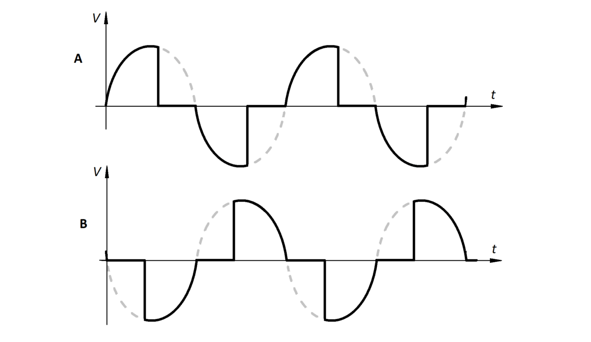
TRIAC dims the light by cutting off a part of AC power sine wave. So, instead of a full power the light gets only a part of it. The illustration below shows how the waves look with (B) and without (A) dimming:

As I have mentioned it is quite old method which best works with incandescent lights. Of course, there are solutions adopted to conventional lights which differs whether the cut off edge is trailing (A, used for capacitive loads) or leading (B, used for inductive, resistive loads) in a sine wave:
Although it can be adopted for different type of lighting there is no guarantee for a full compatibility. Sometimes the light might noticeably flicker or, if several luminaires from different manufacturers are used on the same dimmer – they might not dim down to the same intensity. Also, if we are talking about LED lights, their power supply needs to be compatible (dimmable). Generally LED lamps convert AC current to DC. So, the LED driver needs to convert modified sine waves from a TRIAC to acceptable control means for the LED. There are really two ways how LED intensity could be changed. Either you can change the current flow linearly or you can change average power going through the LED by using Pulse Width Modulation (PWM). The latter being more popular approach.
LED strip control
Let’s get to the main topic – the LED strips and their control method with its pros and cons.
You probably already know what a LED strip is – it is a flexible (usually) strip (duh) of led array. Small strings of LEDs are connected in series while these strings are connected in parallel throughout all strip. The LED strip is usually supplied from a constant voltage (either 12 or 24V) power supply.
LED strip schematic could be drawn as shown below:

Most constant voltage (CV) power supplies are not compatible with regular (TRIAC based) wall mounted dimmers. Actually, it is nearly impossible to find a dimmable CV power supply with would be useable for a particular application. Because there is a bigger choice from non-dimmable PSUs, LED brightness control is executed after the PSU.
As I have already mentioned, most popular LED strip dimming method is PWM. So, to dim a LED strip, additional control circuit (a controller) needs to be used. It is placed between the LED strip and the PSU. In its simplest form, some buttons might be connected to the controller, so by pressing them the LED brightness can be changed. There might be other interaction methods such as a remote control, a mobile app (so control goes through a Wi-Fi or Bluetooth connection), other smart home standards (Z-Wave, Zigbee, KNX etc.).
The PWM cuts out part of the LED power and supplies not constant voltage to the lights but shopped signal:

Pros and cons
The great thing about PWM control is that it is easy to do. Only an MCU with a power transistor is needed to create PWM pulses. So, it means that this control method is quite cheap. Also, if low RDS MOSFETs are used, there are not many losses and thus heat output is low. So, this type of controller can be quite small.
There are some cons. First of all, there might be incompatibilities with power supply units. What I mean, is that usually CV PSUs are not designed to work well with constantly changing load, so with PWM switching there might be high pitched noise coming from the PSU. In reality it does nothing bad to the PSU, but it might be highly distracting to a person. Also, there might be EMI issues as the fast rise and fall PWM edges can create interference to other devices – but rarely anybody bothers with it. Lastly, there is a light flickering which is created by turning on/off the light repeatedly. With it goes some health and machinery reliable behavior issues which will be discussed further.
Flicker in PWM dimming
Flicker is an unsteady movement of a light causing rapid variations in brightness. Depending on the flicker frequency, these brightness variations can be perceived by a human or machinery (such as optical sensors) differently.
How human perceive flicker depends on its frequency. Flicker with frequency up to 60-70 Hz will be distracting or in worst case scenario will cause epilepsy (for individuals susceptible to photosensitive Epilepsy) [1]. Higher frequencies, 70 Hz and above, might cause headaches, eye strain, general fatigue. The longer the individual is exposed to this kind of lighting, the higher chances are to perceive the mentioned health issues.
Also, IEEE standard shows [2] that the higher the frequency of the light flickering the lower risk to get the symptoms. Moreover, modulation depth has an influence whether you will feel the symptoms. The modulation depth is defined as:
Where Lmax and Lmin are maximum and minimum luminance respectively.
If modulation is zero, then there will be no flickering (constant current scenario). When LED strip is driven with PWM control circuit, modulation depth becomes 100 %. In the same standard [2] it is derived, that if the luminaire has 100 % modulation depth, the flicker frequency should be higher than 3 kHz, so the individual will not feel any health symptoms during indefinite exposure times.
The 3 kHz frequency is calculated with the following formula (see [2]), knowing that PWM modulation is 100%:
Avoiding flicker effects
This leads to a conclusion, that if we want to avoid any health-related discomfort with LED strips, we need to use PWM frequency higher than 3 kHz or we could use analog constant voltage/current approach to eliminate the flicker altogether.
Although high frequency (> 3kHz) flicker might be suitable for humans, it is not really an alternative for the machinery. As a study shows [3], camera sensors might require light flickering of 24 kHz or higher to diminish the flickering effect such as uneven frame exposure. Also, particular frequencies might cause stroboscope effect when rotating parts are lit by a flickering luminaire. So, machine vision equipment or machinery with rotating parts should, if possible, use lights with no flicker at all. In this case, only viable dimming method is via constant voltage/current analog approach.
An alternative to PWM dimming which reduces flickering
So, as I have mentioned, alternative to PWM is analog control. It means that there is no voltage/current switching which is sent to the load and LED flicker is maximally reduced.
One of the solutions might be adjustable voltage regulator, such as LM317 or its more powerful alternatives. This kind of control will have a drawback, related to all linear regulators: high power losses and thus generated heat. Also, it will require a heatsink, which in case of high controllable power, might be quite big.
Buck converter
Alternative to linear regulators are switch-mode power regulation circuits. Simplified schema of so-called “buck” converter is shown below:

Its generic buck converter’s schematic. Usually, it is a better to use N-FET or NPN bipolar transistor, so we could redraw the schematic, so the transistor will be on the negative power rail:

Here you can see all needed parts to really make the circuit. The LC filter is designed to work with frequencies above 2.3 kHz. SS54 was used as a flyback diode.
Real circuit
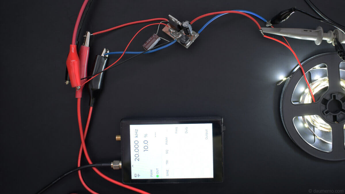
This type of circuit I have built and tested:

The transistor gate was connected to the DIY Generator and driven with 20 kHz frequency. Output voltage (and so the current) was constant. Although I tried to guess, that because LED strip does not glow at voltages below ~7 Volts, it should stop to illuminate at PWM duty set to around 60 %. In reality the brightness changes gradually from 2 % till 100 %. Whole real connection can be seen below:
The main obvious problem with this circuit is that it is hard to fully shut off the LEDs. Because of high output capacitance small LED strip will still glow for a long time (5-10 seconds) as the capacitor discharges slowly. One of solutions might be additional resistor (even 10k helps) acting as a load:

Generally, the output capacitor should be chosen with as small capacitance as possible for a given application.
Finally, it should be noted, that the LED output is not with fully reduced flicker. There are some (around 70 mV) voltage ripple in the output. This ripple is negligible compared to the PWM (which would be 12V):
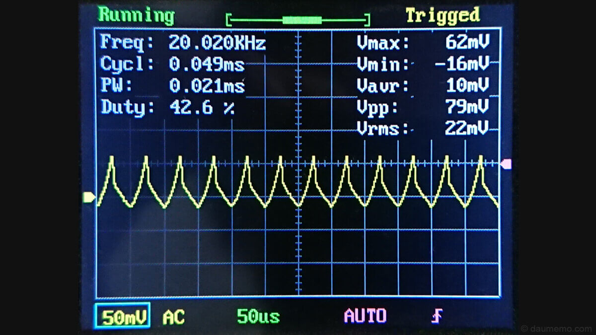
Ripple voltage will depend on load current, LC cut-off frequency compared to PWM frequency (the higher filter cut-off frequency, the lower the ripple).
Circuit adaptation to existing control solutions
Similar circuit can be adapted to existing LED PWM controllers. Most of them already have a power transistor inside and they switch negative LED power rail (similarly as the previous shown circuit). So, if we omit the transistor, we could make a simple filtering circuit for a PWM LED controller which you already have:

The problem with this solution is that it will require high inductance and high capacitance, because most circuits operate at a quite low frequency, usually in 100-1000 Hz range.
Also, to fully turn off LEDs fast, additional load resistor (for example, 10k) could be used:

The filter cut-off (corner) frequency can be calculated as follows:
Where L is inductance and C capacitance. Or you can use my calculator below, to find out the filter’s frequency with given inductor and capacitor values:
Also, the inductor needs to be rated for higher current that the application needs, and capacitor rated voltage needs to be higher than it is used by your LED strips.
Overall, the better solution is when the LC filter is driven by a dedicated high frequency controller, so L and C values can be low. In this case both, the capacitor and inductor will be small.
Here is the test circuit soldered together:

And here is its connection to one of the PWM channels on the DIY 4 channel LED strip controller:

Similarly to the full circuit with the transistor, this circuit combination also has some output voltage ripple (~ 1.3 V):

You should notice, that this ripple has a lot bigger amplitude than previous, 20 kHz circuit. The reason behind it can be that the controller PWM frequency (1 kHz) is similar to LC filter's cut-off frequency (~ 700 Hz), so there is small PWM signal attenuation.
Analog LED control advantages and disadvantages
The main (and probably only) advantage of linear LED control is that it does not produce flicker. This point is also illustrated in the photo below:

In the picture on the left you can see the PWM driven LED, while on the right side – the same LEDs are driven from PWM + LC filter, both at 4% duty. As you should see, there are several horizontal lines of light inconsistency along the PWM-only driven LEDs (left side). These lines are reproduced by the camera sensor. On the right side there are no such lines, which means that there is no flicker in the light source.
Drawback: color-shift
That being said, there are several drawback of the analog control circuit. Let’s see the same photo from a different point of view:

Here is the same photo: left side – PWM, right – PWM + LC filter. Notice, that although light intensities are somewhat similar, but the right side has a bit warmer color. Although it might seem as not much, but in reality, the difference is quite obvious for a naked eye. This is a known behavior of the LEDs – they have color-shift dependence from the electrical current strength. So, the color shift is also observed here. When they are put to 100% PWM, both sides emit the same color and color-shifting is not observed.
Although there is a color-shift on linearly driven LED strips, I have not found much information on how the CRI changes. If the CRI does not change much, the color-shift alone might not be a huge problem.
Drawback: inconsistent light when dimmed to low brightness
Also, in the same photo you should be able to see, that on the right side, LEDs are lit inconsistently: some LEDs emit brighter light while others emit weaker light. PWM-only driven LEDs does not have such behavior. There is no easy walkaround for this problem. The possible solution con be a hybrid system which changes LED brightness to let’s say 5 %, and for everything lower, PWM control kicks-in. Finally, there is a problem when the linearly controlled LEDs needs to be fully shut off. It takes some time for the output capacitance to discharge, so the LEDs glows while capacitor discharges.
Drawback: additional voltage drop
Lastly, a small drawback of the analog regulation could be an additional voltage drop across inductor. In my case it was 0.1V which is practically unnoticeable. Of course, this voltage drop will depend on the selected inductor's resistance.
Summary
In conclusion, PWM control is quite popular LED strip dimming method. Although it is used often and even it is easy to make by DIYers, it has a main drawback – light flicker. Depending on the flicker frequency, such luminaire might cause some health issues: from epilepsy (flicker <100 Hz) to discomfort such as eye strain, headaches (flicker > 100 Hz), to no noticeable health issues whatsoever (flicker > 3 kHz).
Machine vision might sense flicker of frequencies higher than tens of kHz. Also, flicker might cause unwanted stroboscope effect when rotating parts are involved.
So, as the solution to the mentioned problems might be analog LED current (and so the brightness) control. Such solution, if designed correctly, will have no flicker at all. Although, it solves one problem, it also introduces other caveats such as individual LEDs light intensity variation among the strip when dimmed down maximally, possible difficulties to fully turn off the LEDs, color-shifting.
Because suggested method uses a topology similar to a simple voltage step-down converters, possible solutions to the analog control issues might be: minimizing LC filters capacitance and inductance by maximizing PWM switching frequency, additional load in parallel to the LED strip, hybrid linear current/PWM control system.
References
- A. J. Wilkins, J. Veitch, and B. Lehman, “LED lighting flicker and potential health concerns: IEEE standard PAR1789 update,” in Proc. IEEE Energy Conversion Congr. Expo., 2010, pp. 171–178.
- (2010, Feb.). Recommending Practices for Modulating Current in High Brightness Leds for Mitigating Health Risks to Viewers. IEEE Standards Group PAR1789. [Online]. Available: http://grouper.ieee.org/groups/1789/
- Effects of PWM Dimming LED Illumination on Camera Images and Countermeasures. IEEE Standards Group. 2019 IEEE 60th International Scientific Conference on Power and Electrical Engineering of Riga Technical University (RTUCON). 7-9 Oct. 2019.