There are lots of cheap USB-Serial adapters on the market which most of the time are perfect solution if you want to flash a MCU or you need a data connection between a PC and some kind of device with serial interface. But those cheap solutions are not suitable if electrical isolation between a PC and a connected device is needed. In such case, several years ago, I decided to make my own galvanically isolated USB-UART adapter.
The adapter in question has:
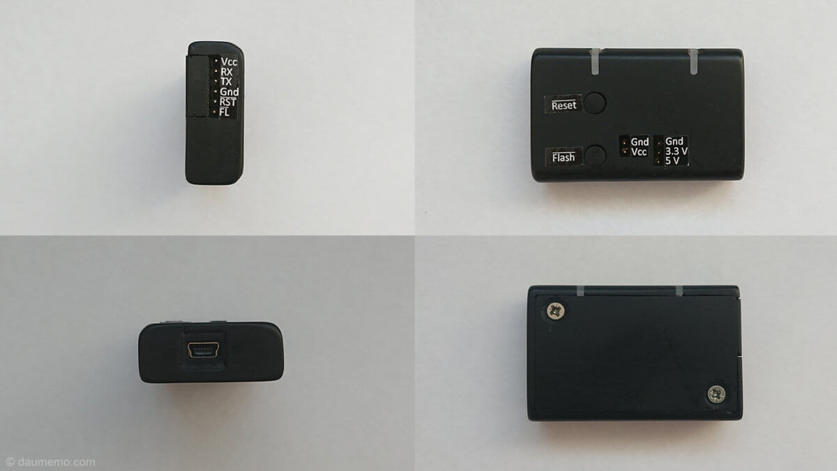
- mini USB port (connection to PC trough USB Type A -> mini USB cable)
- 2 LEDs (Connected device’s power and status indication)
- 6 pin standard header for connecting a device
- 2 additional buttons (can be any function, but in my case RESET and FLASHing)
- 2 headers for supplying connected device with power (if needed)
- FT232RL USB to Serial IC
- Si8621 data signal isolator
- On board 3.3V regulator for powering up connected device

So, firstly let’s talk about connections. The adapter has Mini USB port which is used to connect to a PC. Mini USB was chosen because it is sturdier than micro USB port and smaller than type B port. The adapter has 6 pin header with 2 power pins, 2 RX/TX pins and two additional pins connected to two buttons. You may ask why additional two pins are needed? This adapter was/is mainly used for programming Espressif ESP microcontrollers, so those pins usually connects to ESP pins which are used to put chip into flashing mode or reset it.
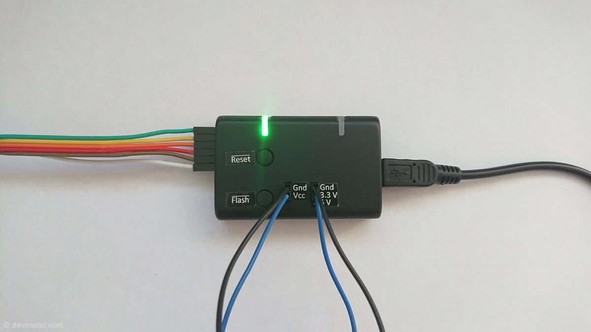
The board also has two power headers. One header connects to the device’s power side, while other connects to PC’s power side. So, when these headers are connected together (via jumper cables) the device will be powered from PC. It is also possible to select needed voltage: 5V or 3.3V by simply connecting jumper wire to the needed one pin.
The adapter has two LEDs. Both LEDs are actually RGB, although not all pins/colors are used. On the device’s side we have Power LED. As the name suggests it shows if the connected device is powered on (green light) or off (no light) and it doesn’t matter if the device is powered by itself or by a PC (LED will always show if there is voltage on the device’s side). The other LED is Status LED. It shows if there is any data transmission happening at the moment. When you connect the adapter to a PC and the adapter is idle, LED lights up in green. When there is data transmission going between the PC and the device – LED lights up in yellow (red + green colors).

The adapter uses FT232RL as main communication IC which translates USB data to UART. As the adapter is quite old FT232RL was used because it was easily available at that moment. Nowadays there are cheaper alternatives to the chip (like Silicon Labs CP2102). As isolation IC Si8621 was used. It has two isolated channels for data transmission – fit perfectly to this case as UART needs only two data lines. This IC is placed between FT232RL and the header to which the device is connected. There is also 3.3V 1A 1117 regulator which is used when a 3.3V voltage is needed to power the connected device instead of USB supplied 5V.
USB-UART adapters PCB was etched at home by ultraviolet lamp method. I have written a tutorial how it can be done either using UV light or with a CNC router.
An enclosure and button covers were 3D printed with black ABS plastic. Inserts for LEDs were made from 2mm thick plexiglass. After printing, enclosure’s parts were screwed together, and LED inserts were glued into slots. Then whole enclosure was sanded down to make its surface smooth and to flatten flush LED inserts with the enclosure’s surface. Finally, labels were printed with regular printer and glued onto enclosure next to the header pins and buttons.
Links to project files:
https://github.com/daumemo/USB-UART-with-galvanic-isolation
https://www.thingiverse.com/thing:3703276