Sometimes you might need to connect two circuits or ICs together, but they operate at different voltages. There are two, known to me, methods, how you can do that – and it is the topic of this post.
Table of contents
Logic levels
First of all, let’s talk about logic levels used in digital circuits. In programming languages, we usually operate with bits, which are 0 or 1. These logic values are also used in data lines connecting different hardware circuits. Of course, in hardware 0 or 1 is just a representation of voltage levels. Circuits, which operate on different power supply voltages, have also different logic voltage values.
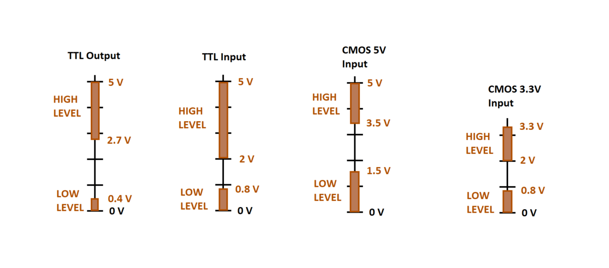
In the picture below, you can see an example on how differs output/input voltage in circuits made by different technology and/or operating on different supply voltages:

Firstly, please note, that I haven’t shown, what CMOS output logic voltage level intervals are, because they highly depend on output currents. Mostly, they are Vcc – 0.5 V for ‘High’ voltage level and 0 – 0.5 V for ‘Low’ level.
You should be able to work it out, that TTL and CMOS logics (either 3 or 5 V) can be more or less interconnected together, because their input voltage logic levels overlap with output voltage levels.
The main problem with 5 V and 3 V circuits are that lower voltage ones are usually not 5 V tolerant, so they will be damaged with higher voltage signal.
Lastly, I want to mention, that the voltage level examples shown in the picture are more for illustration purposes and might not reflect real acceptable input/output voltages of a particular IC. It is always a good idea to check the acceptable working voltage levels in the IC’s datasheet.
Resistor voltage divider
If you have clearly defined signal direction on the lines, you can use a voltage divider on signals which come from higher voltage IC to lower voltage one.

If 3.3V circuit’s input is not 5 V tolerant, the output from the 5 V logic needs to be lowered. One of the methods is to use a voltage divider as it is show in the picture above. With the shown resistor values, the output of five volts will be lowered to around 3.3 volts, which are needed for 3.3 volt input logic.
If you need resistor to play around with such circuits, you can buy it at Aliexpress here (Affiliate).

If you need to connect 3.3 V output to 5 V input, everything is simpler. You need to connect the lines directly (see picture above).
If you have bi-directional signal lines, you will have to use voltage dividers on all signal lines.
To sum up, this might be a simple and inexpensive solution to connect two circuits together, but it might not always work. An example could be two circuits which operate at very different voltages (like 5 V and 1.8 V) and the high voltage circuit won’t read output from the low voltage circuit.
Logic level converter
Another way to connect two circuits with different voltages together is to use a logic level converter. It is usually a small PCB with several transistors soldered in. It drops down signal voltages. Also, it is bidirectional.

Here, how it looks in real life:

The converter is cheap and can be bought at many electronics stores. Here is the link to Aliexpress (affiliate): Voltage Converter.
The converter PCB that I have, has 12 pins: 2 GND, 1 higher voltage supply (HV), 1 lower voltage supply (LV), 4 higher voltage signal in/outs (HV1, HV2, …) and 4 lower voltage signal in/outs (LV1, LV2, …). So, the board can convert voltages between four different signal lines. If you need more lines, you will have to use two or more converter boards.
The connection is straight forward. You connect the PCB between two circuits. An example is shown below, how I personally had connected an Arduino Uno (5V) with an SPI memory IC (3.3V):

Additionally, I have used a 3.3V linear regulator (1117 series) to power the low side of the voltage level converter and the flash memory IC.
Here is the real photo, how everything looked on the prototyping board:

In this case I have soldered memory IC in a home-made PCB. Information, how you can make one yourself, can be found here.
If, for any reason, you would like to use components shown in the photo above, here is the part list (with affiliate links):
- Arduino Nano (Aliexpress)
- Voltage level converter (Aliexpress)
- L1117 linear voltage regulator (Aliexpress)
- Prototyping board (Aliexpress)
- Connection wires (jumpers) for prototyping board (Aliexpress)
Connecting circuits directly
The last method is to connect circuits directly. It is only possible if the lower voltage circuit is high voltage tolerant. Most of them are not, you will need to check the datasheet to see, if such connection is viable. If you by mistake connect two circuits together, where the low voltage one does not tolerate higher voltages – that circuit will be damaged.
Summary
So, these were all possible (and known to me) connection which can be made between different voltage circuit signal lines. Hope, that at least one of them will help you connecting the circuits.


