Yet another step towards finishing the DIY generator. As the previous one, this post is also going to be quite short, because there is not much to write about.
Electronics devices usually have some kind of enclosure, so no exception is my generator. As it is portable device, the housing needs to be as small as it can be made.
Links to project’s all posts
- VCA822 Gain Amplifier Circuit
- LM7171 Offset Circuit
- Gain and Offset Control Filter Circuit
- Dual 5V Power Supply
- Dual 12V TPS65131 Power Supply
- Battery Charging Circuit with BQ24295
- Basic WEB Interface
- IPS Capacitive LCD on an ESP32
- IPS LCD, ESP32 with eSPI library and Touch screen
- Final PCB Design for the DIY Waveform Generator
- Custom Design PCBs and How To Get Them Manufactured
- Soldering the PCB
- AD9833 Library and Further Output Noise Reduction
- Arduino BQ24295 Battery Charger Library
- LCD GUI with LVGL on ESP-32
- 3D Printed Enclosure (this post)
- Finished DIY generator
The Enclosure
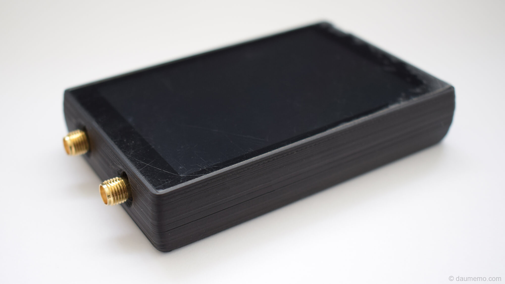
So, here it is:

The waveform generator is a small but chubby device, measuring about 95 x 60 x 18 mm (excluding SMA ports). Note, that there is still a protective film on the screen.
All main parts are ‘sandwiched’ together. The construction can be seen in the photos below.

The enclosure is printed as a single peace part, except the cutout for the power switch. This cutout needs to be closed with another small cover.
Construction
So, on the top is the LCD screen. It is going to be glued in during final assembly. Take out the screen and you will find the PCB. The PCB fits with 0.5 mm margins to the enclosure. So, it needs some kind of additional holder to keep it in place (or it could be also glued in during final assembly). Finally, after taking out the PCB you will see the battery in the bottom. The battery will be held in place with double sided tape.

There are two SMA connectors on one device’s side. One connector is used to output sine/triangle/square waves with changeable offset and amplitude. Through the second SMA port, PWM signal (amplitude 0-3V) can be transmitted. This one is useful when you want to connected the generator to some kind of logic device without worrying too much about the offset or amplitude values which might damage the connected device.
On the other side there is an USB Type C port used for charging the battery. To the left from this port, there is a small hole with an LED behind it. It is used to indicate the battery charging/finish state. To the right from the USB port, there is a power switch which turns on/off the device.

Moreover, this enclosure took several tries to get near the final version (photo below).

PCB
I think, I haven’t shown fully assembled PCB yet, so here it is:

It finally has SMA connectors, relay and the switch soldered in.
Lastly, for now I am not going to give access to the enclosure’s STL files as they might change a little in the final version. After the generator will be fully assembled, all files is going to be available to download.